Plug-and-play, Connection diagram, Specifications – Hall Research 400 User Manual
Page 3
Page
3
of
4
Plug-and-Play
DDC (Direct Data Channel) is a standard by which a compatible monitor sends its
identification and other parameters to a PnP operating system such as Windows 98 etc. Only
one of the monitors connected to the splitter is allowed to communicate with the operating
system. This means that the user should ensure that either all the monitors can support the
resolution which will be set or disable the DDC and force any desired resolution and refresh
rate from the “Display Properties” screen of the operating system. If upon connecting the
Splitter you get a blank screen, it could be that your PC is looking for a monitor but cannot find
any. In this case, either plug a monitor directly to the PC and disable PnP (by choosing a
different standard-type monitor), or have at least one monitor plugged in to the specific output
of the splitter that is assigned to the DDC channel (see Specifications for details).
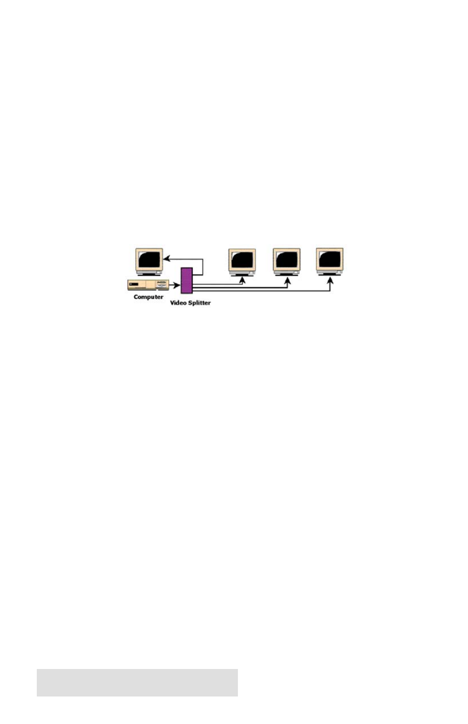
Connection Diagram
Specifications
Equipment included:
• UL approved 110 VAC adapter (6 VDC @ 300 or 800 mA output)
• 6 ft, high-resolution (multi-coaxial) video input cable
• User’s Manual
Dimensions:
L x W x H:
Model 200 - 4¼ x 2¾ x 1¼ Model 400 - 7¼ x 2¾ x 1¼ Model 800 - 7¼ x 2¾ x 2¼
Video Specs:
Connectors
Input and Outputs: HD15 female
Coupling
DC
Signal Level
Video: 0.7 v p-p
Bandwidth:
Range: DC to 250 MHz
Input impedance: Video: 75 ohms on RGB, 1K ohms on H, V
Plug-n-Play:
DDC-Channel from Monitor to PC is on the following output positions:
Model 200 – Output #1 Model 400 - Output #4 Model 800 - Output #8