页 10 – Grandview GPCK-MB User Manual
Page 10
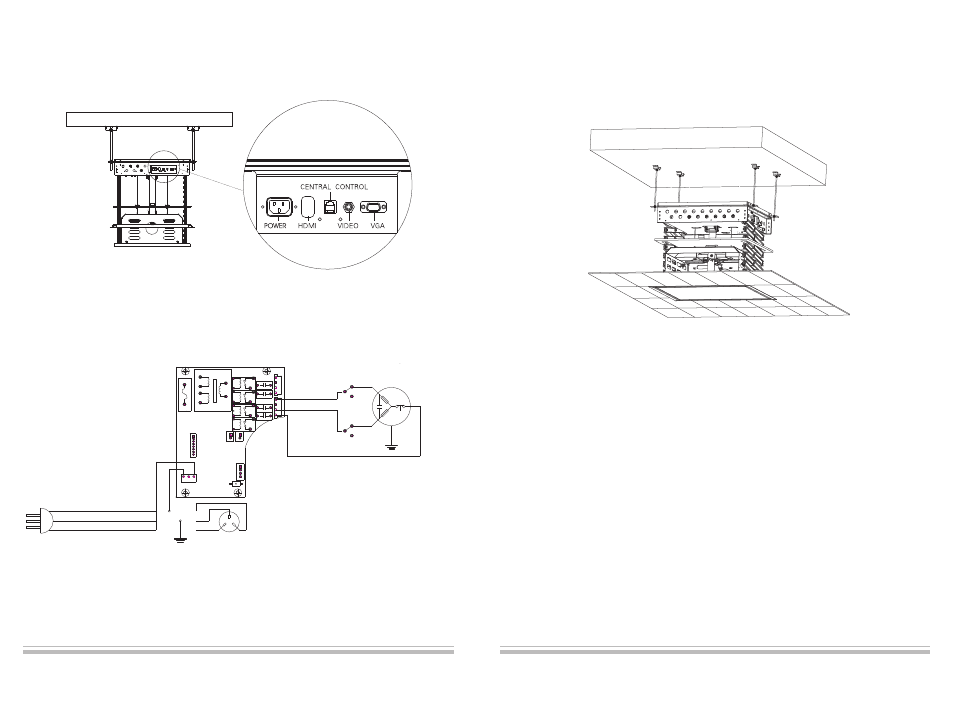
7. Figure 15,connect the power cord and signal cord(Circuit wiring diagram 16)
Figure 15
Brown line
Yellow and Green Line
Circuit
Board
Socket
Blue Line
7. Cut the ceiling board (Step 1) to a suitable size which can accommodate the gap after the projector lift is
retracted.
Figure 17
8. Please read the "Remote Electric Positioning" section for controlling the projector lift. After the adjustment,
ensure the height of the projector lift is set to your needed specifications. Ensure the bottom of the projector
lift is aligned with the ceiling after it's retracted. Note: the operation of this lift must be operated by a qualified
professional.
9
Figure 16
Brown line
Black Line
Black Line
Brown line
Blue line
Yellow and
Green Line
10