12 commissioning, 4 initial lighting, 5 check the gas inlet pressure and gas rate – Glow-worm Ultracom cxi User Manual
Page 39
39
Commissioning should only be carried out by a
competent
person approved at the time by the Health and Safety
Executive.
12.4 Initial Lighting
NOTE: The combustion for this appliance has been
checked, adjusted and preset at the factory for operation
on natural gas (G20) as defined on the appliance data
label.
No measurement of the combustion is necessary.
Having checked :
● the appliance has been installed in accordance with the
instructions.
● the integrity of the flue system and flue seals.
● the integrity of the appliance combustion circuit and
relevant seals.
● that all internal/external controls are calling for heat.
● the gas service isolation valve ‘F’, diagram 12.2, is open.
LPG Conversion:
See section 12.9.
Light the appliance by following the procedure below:
Select the “Constant central heating with DHW” function by
pressing the “Mode” button repeatedly to scroll through your
options until constant central heating with domestic hot water
is shown
, see diagram 12.1
● The appliance will enter a self checking routine, then the fan
will start and the ignition sequence commence.
The boiler, if necessary, will automatically repeat the ignition
sequence a further 4 times.
● If the burner fails to ignite “F1” will be displayed, initially, this
may be due to air in the gas supply line.
● Press the “
“ central heating water temperature button
and the factory setting temperature will be displayed.
Press “+” (plus) or “-” (minus) buttons to adjust.
● Press the hot water temperature “
” button and the
factory set 40
O
C temperature will be displayed.
Press “+” (plus) or “-” (minus) buttons to adjust.
Open a hot water tap, the display will indicate the domestic
hot water temperature.
Check that hot water is available at all taps, then close.
12.5 Check the Gas Inlet Pressure and Gas
Rate
The supply from the governed meter must be of adequate
size to provide a steady inlet working pressure of 20mbar (8in
wg) at the boiler. On completion, test the gas installation for
tightness using the pressure drop method and suitable leak
detection fluid, purge as necessary.
NOTE: Due to the modulating operation of the boiler and
the need to check the gas inlet pressure and measure the
gas rate at maximum rate, it will be necessary to force it to
maximum.
Press the “reset” button on the controls fascia, release
and immediately press and hold in the “+” button. After
approximately 5 seconds “Hi” will be displayed. Pressing
the mode button when “Hi” is selected will force the boiler
to maximum rate, the display will flash between “Hi” and the
“default display” this will indicate the boiler has been forced to
maximum.
12 Commissioning
Operational Gas Inlet Pressure
With ALL other gas appliances operating, check the
operational supply pressure at the gas service isolation valve
test point, see diagram 12.2.
The nominal supply pressure for Natural Gas (G20) is 20mbar.
The nominal supply pressure for LPG (G31) is 37mbar.
Turn the taps and appliances off, then disconnect the pressure
gauge.
Additionally the safe nominal maximum heat input of the
appliance can be achieved at an inlet pressure down to
15mbar.
NOTE:
The
BURNER PRESSURE cannot be measured and
is not used to measure the gas rate.
Gas Rate
Make sure that ALL other gas burning appliances and pilot
lights are off.
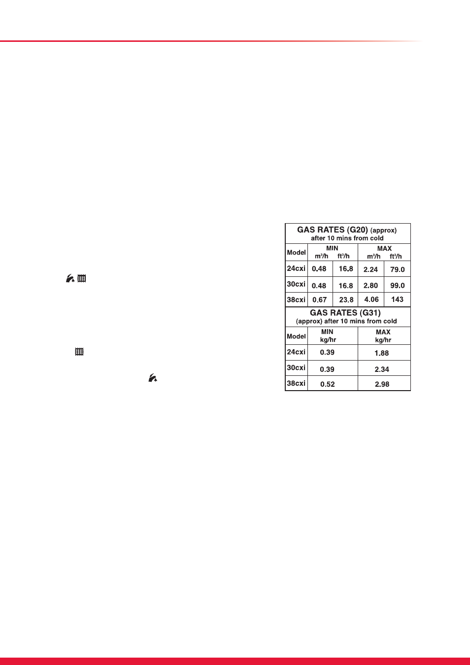
Check the gas rate using the gas meter test dial and stop
watch, at least 10 minutes after the burner has lit, see table
below for approximate rates.
15439
In communal or LPG installations where the gas rate cannot
be measured it is acceptable to measure the combustion rate
as described in the servicing section.
On completion, press the “mode” and “+” buttons
simultaneously, this will reset the boiler.