10 replacement of parts – Glow-worm Ultimate 50BF User Manual
Page 25
25
221790B
10 Replacement of Parts
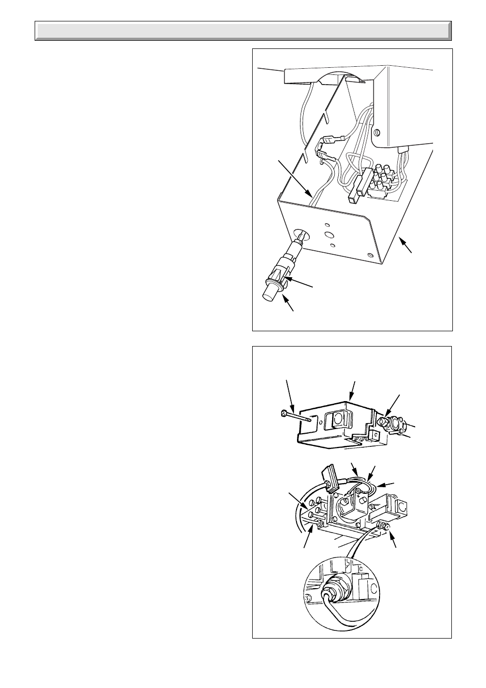
Note: To ease the removal of the piezo unit it is advisable to
temporarily remove the boiler thermostat from the control box,
refer to Section 10.1.
Depress the retaining tabs and remove the Piezo unit.
10.5 Thermocouple - diagram 10.3
Proceed as relevant parts of Sections 8.2 and 8.5.
Unscrew thermocouple nut.
When refitting do not tighten the thermocouple nut more than a
quarter turn beyond finger tight.
10.6 Multi-functional Control - diagram 10.3
Remove the screw to release the multi-functional control cover.
Disconnect the electrical leads, thermocouple and pilot supply
pipe at the valve.
Undo the four screws each side of the multi-functional control to
release the gas service cock and the burner supply pipe, take
care not to damage the “O” ring seals.
Remake the connections.
Do not tighten the thermocouple nut more than a quarter turn
beyond finger tight.
It will be necessary to purge the pipework and the multi-
functional control before relighting, refer to “Commissioning”.
Refit multi-functional control cover.
10.7 Solenoid - diagram 10.4
With the multi-functional control cover removed disconnect the
electrical leads, remove the retaining clip and solenoid.
10.8 Main Burner
Remove the main burner as Section 8.2.
10.9 Main Injector
Remove the main injector as Section 8.4.
10.10 Insulation - diagram 10.5
Combustion Chamber Front
Remove the combustion chamber front as Section 8.2. Remove
the retaining screw and slide the insulation out. .
Sides
Slide the insulation pads out.
Rear
With the side pads removed the rear pad can now be removed.
10.11 Viewing Window - diagram 10.6
Remove the old self adhesive aluminium foil gasket and the old
mica window. Replace with a new mica window. Peel off the
backing paper and secure with new self adhesive aluminium foil
gasket, see diagram 10.6. Ensure no air bubbles are trapped
underneath the foil.
Important
Make sure that the mica window fully covers the opening and
that the hole in the aluminium foil gasket is centred over
opening.
Diagram 10.2
Diagram 10.3
8039
3819
CONTROL
BOX
IGNITION
LEAD
RETAINING
TABS
PIEZO UNIT
COVER
BURNER
SUPPLY
PIPE
COVER
SECURING
SCREW
GAS
SERVICE
COCK
BLUE GREEN/YELLOW
BROWN
THERMOCOUPLE
NUT
PILOT SUPPLY
PIPE