8 servicing 9 fault finding – Glow-worm Micron 80FF User Manual
Page 21
21
2000225230C
B
A
A
B
IMPORTANT: Where the flue has a rear connection (from
back of casing), see diagram 5.6, it is essential to make
certain that the flue duct is fully located into the fan elbow
until it can go no further, enabling the flue duct to make a
complete seal when secured.
8.4 Injector Manifold
With the burner removed the injector manifold can be inspected
and cleaned as necessary, see diagram 8.4.
For cleaning do not use a wire or sharp instrument on the holes.
If any injectors are removed, use a little suitable sealant on the
external thread when refitting to make sure a gas tight seal is
made.
8.5 Operational Checks
After completing a service and before fitting the case, check
condition of the case seal and renew if necessary.
Examine flue hood and terminal to make sure they are clean
and clear of obstructions.
Refit all parts.
Light the boiler and carryout the functional checks as described
in Section 6.
Testing Flue Gases: If any doubt exists that the flue products
are not exhausting correctly, investigate by use of a gas
analyser (FGA).
8 Servicing
9 Fault Finding
9.1 Electrical
IMPORTANT: On completion of the Service/Fault Finding task
which has required the breaking and remaking of the electrical
connections the earth continuity, polarity, short circuit and
resistance to earth checks must be repeated using a suitable
multimeter.
Refer to: Boiler Fault Finding, see diagram 9.3, Pump Overrun
Fault Finding, see diagram 9.2, Fault Finding Wiring Diagram,
see diagram 9.4, Pictorial Wiring Diagram, see diagram 9.5.
9.2 Electrical Supply Failure
Failure of the electrical supply will cause the burner to go out.
Operation will normally resume on the restoration of the electrical
supply.
If the burner does not relight after an electrical supply failure the
overheat device may need resetting.
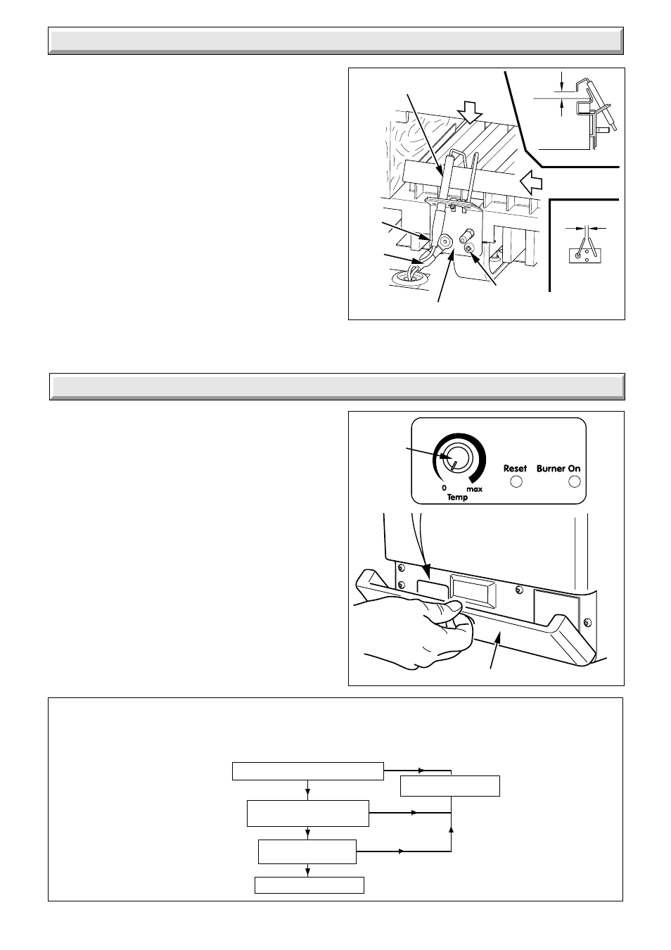
Open the control cover, see diagram 9.1 and if the RESET neon
is lit, turn temperature control on the front of the control box to
“0”, and then back again, see diagram 9.1.
If the safety temperature limiter operates at any other time, do
as above, the burner should relight. If the fault persists refer to
fault finding chart.
CONTROLS COVER
7166
Diagram 9.1
CONTROL
KNOB
6771
Diagram 9.2
Diagram 8.5
12274
ELECTRODE
RETAINING BRACKET
SCREW
HT
LEAD
EARTH
LEAD
6 ± 2
3.5 ± 0.5
Does pump continue to run
after SL is interrupted?
YES
Does pump stop after
several minutes?
System satisfactory.
Faulty PCB. Replace
NO
YES
YES
NO
NO
Does the pump run when SL is applied ?
Pump Overrun Operation
The PCB has a timed pump overrun facility.
The pump should run for several minutes after remote controls have stopped calling for heat.
Before using the fault finding chart ensure all wiring is correct and in good condition, the pump is not faulty and check the PCB fuse.