8 servicing – Glow-worm Hideaway 80BFF User Manual
Page 21
21
221958B
TOGGLE
LATCHES
FAN
Diagram 8.5
0000
8 Servicing
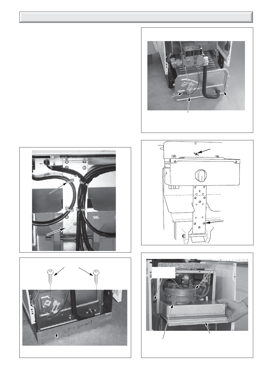
Note: When replacing the fan access door make sure the lip at
the top of door fits into and behind the slotted bracket located at
the top of the boiler.
Note: To ease removal of the right hand baffle from the heat
exchanger, remove both silicone tubes from the air pressure
switch.
Remove fan securing screw, electrical connections and air
pressure tubes, then remove fan by sliding back to disengage
the retaining lugs then lift up, see diagram 8.7.
Remove the flue hood.
When replacing the flue hood ensure that it rests on the guides
and that the rear of flue hood is located under the pegs at the
rear and pushed down and back fully.
IMPORTANT: When re-fitting fan check that it fits fully into the
flue duct extension piece.
COMBUSTION
CHAMBER
COVER
IGNITION AND
EARTH LEADS
GROMMET
Diagram 8.6
0886
WING NUT
SELF
TAPPING
SCREWS
(3)
Diagram 8.7
Diagram 8.4
0000
BOTTOM PLINTH
PANEL
0000
Diagram 8.3
0000
ELECTRICAL
WIRE
RETAINING
CLIPS
CONTROL BOX
SUPPORT
BRACKET
SECURING SCREWS
SECURING
SCREW
FLUE HOOD
- 12-38hxi Range (44 pages)
- 18-30sxi Range (48 pages)
- 23c (44 pages)
- 24-38CXI Range (52 pages)
- 30ci Plus (56 pages)
- BBU 45/4 (32 pages)
- BBU 54/4 (32 pages)
- Betacom C (68 pages)
- Betacom2 (8 pages)
- Betacom2 (20 pages)
- Betacom2 (56 pages)
- Black Beauty 4 (20 pages)
- Chatsworth 4 (24 pages)
- Clearly Heat Recovery (20 pages)
- Clearly Heat Recovery (32 pages)
- Clearly Heat Pumps Envirosorb3 (28 pages)
- Clearly Heat Pumps Envirosorb2 (44 pages)
- Clearly Heat Pumps 7kW (44 pages)
- Clearly Heat Pumps 5kW (28 pages)
- Clearly Heat Pump 5kW (16 pages)
- Clearly Heat Pump 5 kW (32 pages)
- Clearly Heat Pump - Buffer Vessel (10 pages)
- Clearly Heat Pumps - Standalone Module System (40 pages)
- Clearly Heat Pumps - Standalone System (28 pages)
- Clearly Hybrid - Universal Module (20 pages)
- Clearly Hybrid - Universal Module System (36 pages)
- Clearly Hybrid - Compact Hydraulic Module (12 pages)
- Clearly Hybrid - Compact System (36 pages)
- Clearly Hybrid - Compact Hydraulic Module HB (16 pages)
- Clearly Hybrid - Back-up Module System (40 pages)
- Clearly Solar System Hydraulics (28 pages)
- Clearly Solar System (28 pages)
- Clearly Solar Controller (28 pages)
- Clearly Solar Horizontal On-Roof Collector (16 pages)
- Clearly Solar Vertical On-Roof Collector (16 pages)
- Clearly Solar Cylinders (32 pages)
- Clearly Solar - A-Frame (28 pages)
- Clearly Solar Horizontal In-Roof Collector (32 pages)
- Clearly Solar Vertical In-Roof Collector (44 pages)
- Clearly Solar Collector Container (8 pages)
- Climapro 1 (12 pages)
- Climapro2 RF (16 pages)
- Climapro2 RF (24 pages)
- Climapro2 RF (36 pages)
- Climapro2 RF (32 pages)