4 installation – Glow-worm Hideaway 80BFF User Manual
Page 13
13
221958B
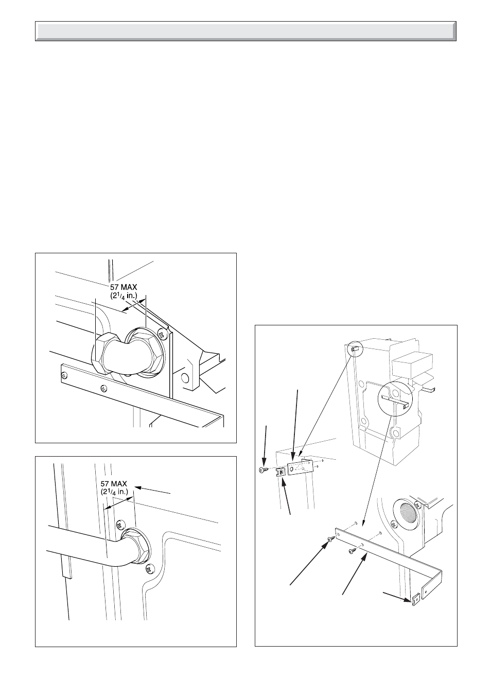
CASING BRACKETS FITTING
Diagram 4.12
9858
FRONT
CASING
BRACKET
No.8
SCREW
(4)
CAPTIVE
NUT
UPPER CASING
BRACKET
CAPTIVE
NUT
4.8 Pipework
When the front tappings are used, it is essential that any
pipework or fittings do not project more than shown in diagram
4.10.
When using a rear tapping with Rc (1in BSP) fitting for 28mm od
pipework, it is recommended that a short nipple and an Rc
thread (BSP) to copper elbow is used. If the pipework is required
to run back to the wall, make sure that it will clear the boiler air
duct and, if working to minimum clearance, does not project too
far from the boiler, see diagram 4.11.
Do not route any pipework, water or gas, across the front of the
combustion chamber cover.
The gas pipework must be along the left hand side of the boiler.
4 Installation
No.8
SCREW
(4)
4.9 Casing Brackets
Fit the two upper and two front casing brackets shown in
diagram 4.12, using the No.8 screws provided.
NOTE: The screws will already be fitted.
Push the captive nuts, supplied loose, on to the casing brackets
as shown in diagram 4.12.
Diagram 4.10
PIPEWORK CASING
CLEARANCES
Diagram 4.11
REAR CONNECTION
PIPEWORK (28mm)
9861
FOR MINIMUM
CLEARANCE
9860