8 servicing – Glow-worm Hideaway 60CF User Manual
Page 16
16
221809B
REMOVAL OF BURNER FROM
COMBUSTION CHAMBER
8 Servicing
Diagram 8.5
BURNER SERVICING
Diagram 8.6
1002
8.2 Burner and Injector
Follow instructions to remove the front cover, burner and controls
assembly as Section 8.1.
Remove the screw securing the lint arrester gauze to the
combustion chamber cover. Remove arrester by lifting slightly
and withdrawing forwards to clear gas pipe, thermocouple and
pilot tube, see diagram 8.5.
Remove the two burner securing nuts from the flange of the
burner supply pipe.
Remove the burner from the cover and supply pipe flange.
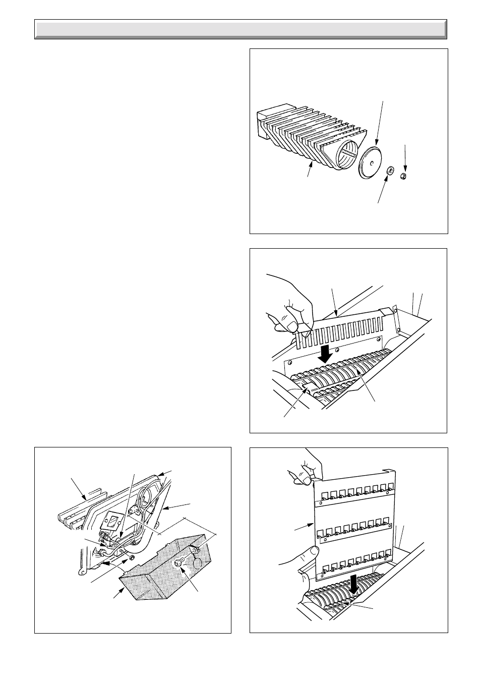
Remove the securing nut,washer an burner end cap from the
burner, see diagram 8.6.
Clean the burner parts and lint arrester thoroughly, using a
vacuum cleaner.
Check the main burner injector for blockage or damage and
replace as necessary, see Section 9.2.
When replacing lint arrester locate the two lugs into the slots on
the combustion chamber cover and locate around the feed pipe,
then secure with the screw.
8.3 Service Checks
Inspect the pilot burner, thermocouple and pilot burner, cleaning
as necessary. Check the condition of the parts. If necessary
remove the pilot shield by removing the securing screw and nut.
Check the condition of the side and rear insulation panels in the
combustion chamber.
Check the condition of the seals on the cleaning door and the
combustion chamber cover.
Replace all items in the reverse order, relight and test the boiler.
SECURING
SCREW
LINT
ARRESTER
SECURING
NUT(2)
PROTECTIVE
SLEEVING
MAIN
BURNER
INJECTOR
COMBUSTION
CHAMBER
COVER
1011
BURNER
SUPPLY
PIPE
BURNER
BODY
BURNER
END CAP
WASHER
SECURING
NUT
Diagram 8.8
6122
BAFFLES
HEAT
EXCHANGERS
HEAT EXCHANGERS
Diagram 8.7
6121
SIDE
BAFFLE
BAFFLE