9 replacement of parts – Glow-worm Hideaway 120BF User Manual
Page 20
20
221765B
9 Replacement of Parts
Disconnect the lead at the spark electrode, see diagram 9.2.
When reconnecting lead make sure that the clear end is fitted
to the spark electrode.
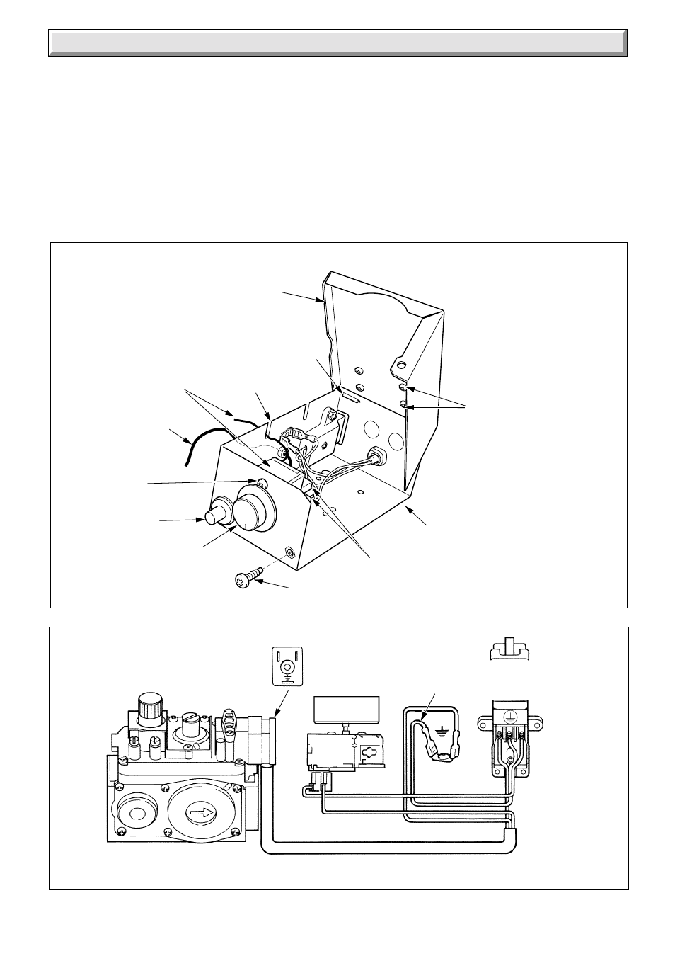
9.10 Electrical Control Box
Gain access to the boiler as Section 8.1.
Disconnect the mains inlet connector, see diagram 8.1.
Remove the retaining split pin from the phial pocket then
withdraw phial and capillary, see diagram 4.5.
Disconnect the gas valve plug from the valve, see diagram 9.1.
Release the control box by removing the securing screw located
at the top of control box and unhooking at the bottom, see
diagram 9.4.
Pull the ignition lead off piezo unit, see diagram 9.4.
When refitting control box make sure the thermostat capillary is
positioned so that it passes through the cut out in the control
box, see diagram 9.4.
Refit thermostat phial, refer to Section 8.5.
7995
ELECTRICAL
CONNECTORS
ELECTRICAL
CONTROL BOX
COVER
COVER
SECURING
SCREW (4)
ELECTRICAL
CONTROL BOX
THERMOSTAT
SECURING
SCREW (2)
THERMOSTAT
CONTROL KNOB
PIEZO
UNIT
HOOK
IGNITION LEAD
(BLACK END)
CUT-OUT FOR
CAPILLARY
SECURING SCREW
THERMOSTAT
AND CAPILLARY
Diagram 9.4
CONTROL BOX
Diagram 9.5
CONTROL BOX AND GAS VALVE WIRING
6284
CHASSIS
EARTH
230V~ 50Hz
MAINS SUPPLY
FUSED AT 3A
BLUE
BLACK
GREEN / YELLOW
BROWN
C
THERMOSTAT
GAS VALVE
N
E
N
L
VIEW OF PLUG
WHEN REMOVED
L
GREEN/
YELLOW
N/C