8 servicing 9 replacement parts – Glow-worm Hideaway 120BF User Manual
Page 18
18
221765B
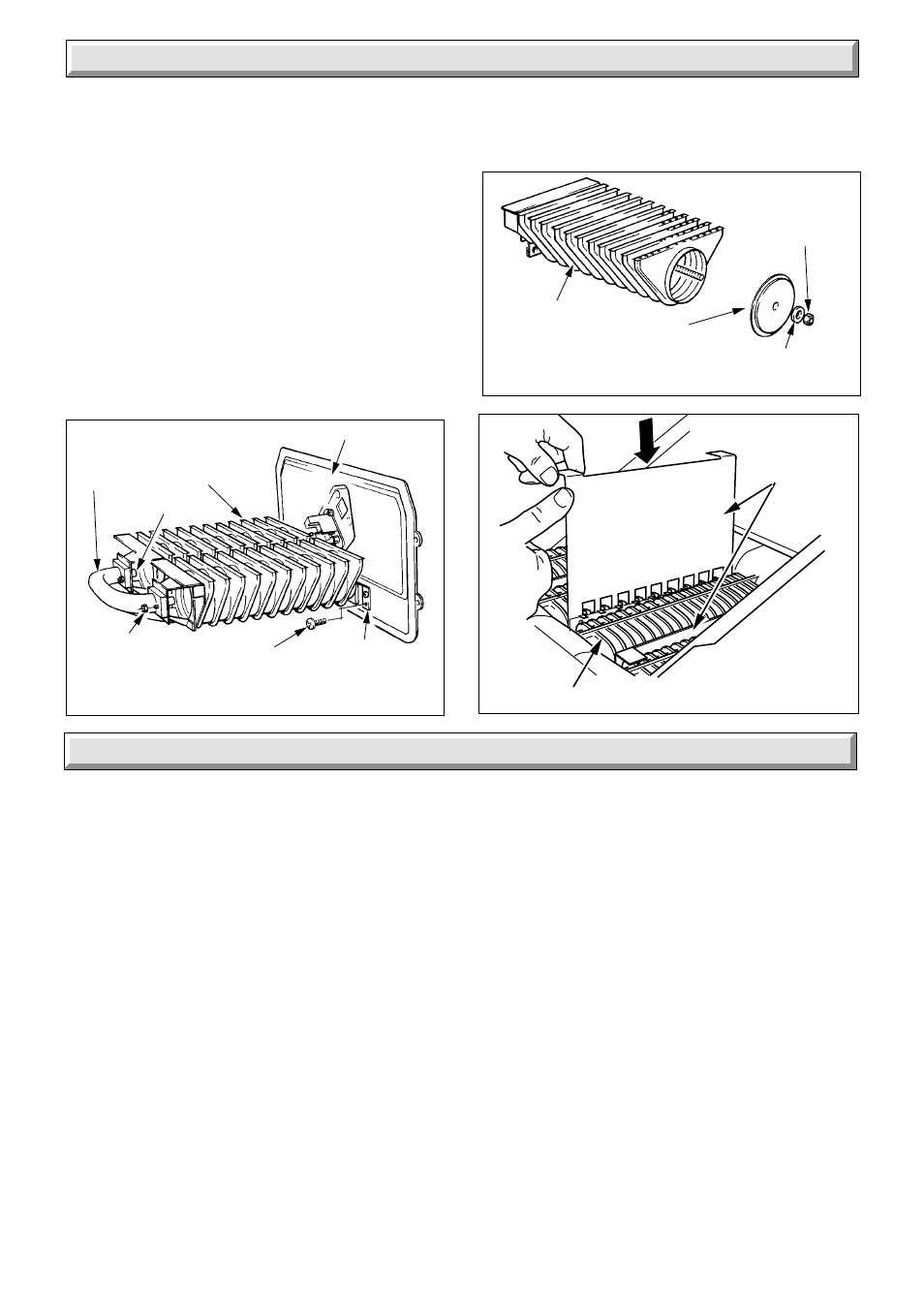
8 Servicing
9 Replacement Parts
6039
Diagram 8.4
REMOVAL OF BURNER
COMBUSTION CHAMBER
COVER
SUPPLY
PIPE
MAIN
BURNER (2)
INJECTOR (2)
GRAPHITE
COATED NUT (2+2)
SCREW
(2+2)
BURNER
SUPPORT
BRACKET (2)
BURNER SERVICING
Diagram 8.5
6040
BURNER
WASHER
SECURING
NUT
BURNER
END CAP
Diagram 8.6
6143
BAFFLES
HEAT EXCHANGERS
Check the condition of the insulation panels in the combustion
chamber, renew if necessary.
Check the condition of the seals on the cleaning door and the
combustion chamber cover, renewing if necessary.
8.5 Re-assembly
Make sure that the baffle tray is replaced and secured with the
graphite coated nuts, previously removed.
Make sure that the thermostat phial is fully inserted into the phial
pocket and secured, with the location washer behind the
retaining split pin, see diagram 4.5.
Make sure flueway baffles are positioned as diagram 8.6
8.6 Operational Checks
Light the boiler and carryout the operational checks as described
in Sections 7.2 and 7.3.
Before removing or replacing any parts, turn the gas off at the
gas service cock, see diagram 8.1 and isolate the electrical
supply to the boiler.
ALWAYS test for gas soundness after replacing any gas
carrying component.
Unless stated otherwise replacement of parts is in the reverse
order to removal.
9.1 Gas Valve
Gain access to boiler, see Section 8.1.
Disconnect the gas valve plug, thermocouple nut and pilot tube
connections at the gas valve, see diagram 9.1.
Support the valve and remove the four right-hand flange screws
to disconnect the gas valve from the burner supply pipe.
Ease the gas service cock union out and remove the valve
taking care not to damage the “O” ring seal at the flange.
Inspect the condition of the “O” ring seal and renew if necessary.
Remove the union half and refit into the replacement valve on
the inlet, left-hand side. Use a little jointing compound, on the
external thread only, to ensure gas soundness.
It will be necessary to purge air from the gas line after changing
the gas valve, refer to Section 7.2.
9.2 Injectors
Gain access to the boiler as Section 8.1
Unscrew the injectors from the manifold and renew as necessary.
When replacing the injectors use a little jointing compound, on
the external thread only, to ensure gas soundness.
Replace thermostat phial as Section 8.5.
9.3 Thermocouple
Gain access to the boiler as Section 8.1.
Disconnect the thermocouple by unscrewing nuts at the gas
valve and pilot burner, see diagrams 9.1 and 9.2. Withdraw the
thermocouple.
When replacing tighten the thermocouple nut only a quarter turn
beyond finger tight.
9.4 Pilot Burner
Gain access to the boiler as Section 8.1.
Remove the cover and burner controls assembly, as Section 8.2.
Disconnect the ignition lead at the electrode, see diagram 9.2.
Disconnect the thermocouple nut at the pilot burner.
Disconnect the pilot tube nut, ease out the tube and injector
which is hooked on to the pilot tube.