14 replacement of parts – Glow-worm Compact 75E User Manual
Page 39
39
221895A
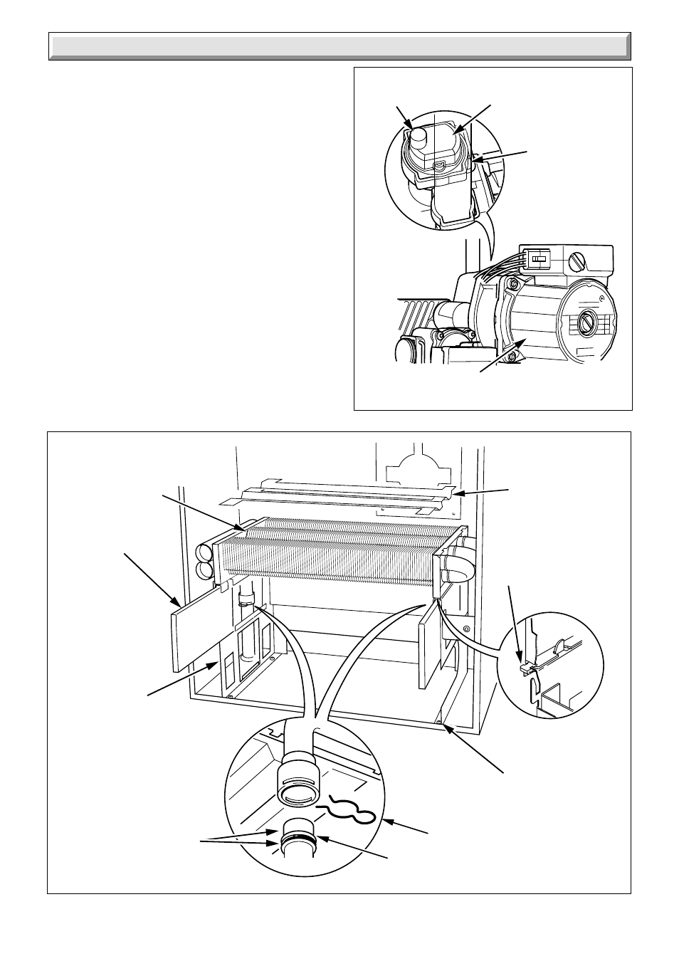
14.25 Automatic Air Vent
Before starting refer to Section 11.
Remove the automatic air vent, see diagram 14.23.
SLACKEN THE SMALL CAP ON THE AIR VENT. THIS MUST
NOT BE RE-TIGHTENED.
14.26 Heat Exchanger
Before starting refer to Section 11.
Unhook the combustion chamber front, see diagram 8.2.
Remove the fan and flue collector, refer to Section 14.1.
Remove the burner see Section 14.2.
Refer to diagram 14.24 and remove the two side insulation
pieces.
Remove the pipe securing clips on the inlet and outlet pipes.
Remove the combustion chamber main panel securing screws.
Remove the heat exchanger/combustion chamber assembly.
Remove heat exchanger front retaining clips.
Remove the heat exchanger from its retaining tabs positioned
at the rear by easing it forward and up.
Replace heat exchanger making sure that it is correctly engaged
on the retaining lugs at the back of the combustion chamber,
carefully refit the pipe securing clips and front retaining clips.
14 Replacement of Parts
Diagram 14.23
7494
AUTOMATIC AIR VENT
Diagram 14.24
9374
PIPE
SECURING
CLIP (2)
HEAT
EXCHANGER
BAFFLE
SIDE INSULATION (2)
FRONT
RETAINING CLIP
(2)
COMBUSTION
CHAMBER MAIN
PANEL
SECURING
SCREW (4)
SECURING
CLIP
PUMP
AIR VENT
CAP
BEADING
'O' RING