8 mounting the boiler – Glow-worm Compact 75E User Manual
Page 18
18
221895A
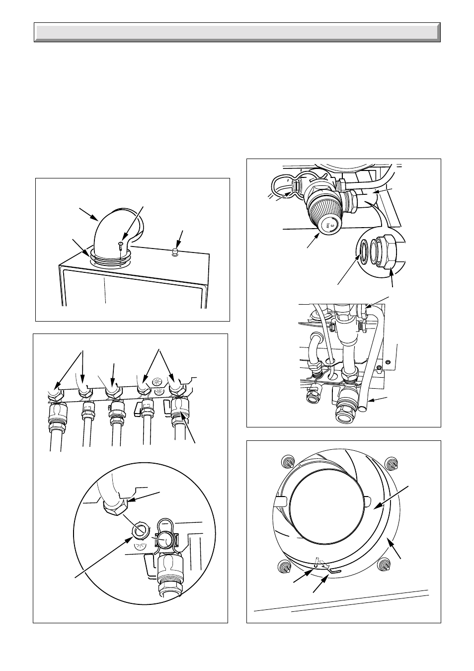
Diagram 8.10
AIR
DUCT
FLUE
SPIGOT
TAB (2)
CUTOUT (2)
7305
8.6 Top Outlet Side or Rear Flue Fixing
Position the restrictor plate supplied in the loose items pack,
between the flue elbow and boiler , (gasket facing upwards). Fit
the flue elbow to the restrictor plate and top of the boiler using
the four screws supplied, see diagram 8.7.
Tighten the four screws of the flue elbow evenly to ensure a
good seal at the gasket.
Note: It is important the correct restrictor plate is fitted or omitted
where instructed.
For top flue outlet be sure to use the correct restrictor plate, all
restrictors are supplied with the appliance, see restrictor table.
7022
Diagram 8.9
UNION CONNECTION
DISCHARGE
PIPE
8 Mounting the boiler
SAFETY
VALVE
DISCHARGE
SEAL
PRESSURE
GAUGE
CONNECTION
DISCHARGE
PIPE
7405
Diagram 8.7
Fit the air duct into the flue spigot by pulling the air duct into the
flue spigot, locating cutouts. Turn the air duct anti-clockwise to
lock into the cutouts, see diagram 8.10.
Note: It is important the correct restrictor plate is fitted or
refitted, see restrictor table.
Fit the flue connecting sleeve onto the fan, see diagram 8.11.
Fit the fan to the flue ducting, see diagram 8.11.
Fit the fan and flue collector the electrical connections and air
pressure tubes to the fan.
Refit the combustion chamber panel.
Make the outer wall weatherproof. A Flue Collar Kit Part No.
443286 is available.
RESTRICTOR/
GASKET
FLUE ELBOW
(REAR FLUE
SHOWN)
SECURING
SCREW (4)
PRODUCTS
PROBE
8080
Diagram 8.8
SERVICE
COCKS (4)
GAS SUPPLY
SEALING
WASHER (4)
(INSERT INTO
TUBING NUT)
FITTED TO HYDRO BLOCK
TUBING
NUT