Eskimo 15400 User Manual
Page 5
5
Check for parts online at
www.GetEskimo.com or call 800-345-6007 M-F 8-5 CDT
Operator’s Manual
ESKIMO
®
QuickFlip
™
2
VERSA SEAT INSTALLATION
6. Attach the (2) seat rails (11200) and (2) support shims (11230)
through holes #2 and #4 on the tub support strap (69677) us-
ing (4) ¼-20 x 1” bolts, (4) ¼-20 nylock nuts and (8) ¼” washers.
Align the slots on the first seat rail (11200) with hole #4 on
the tub support strap (69677) and secure it with (1) ¼-20 x
1” bolt, (1) ¼-20 nylock nut and (1) ¼” washers. Repeat with
other seat rail on hole #2. SEE FIGURE 3
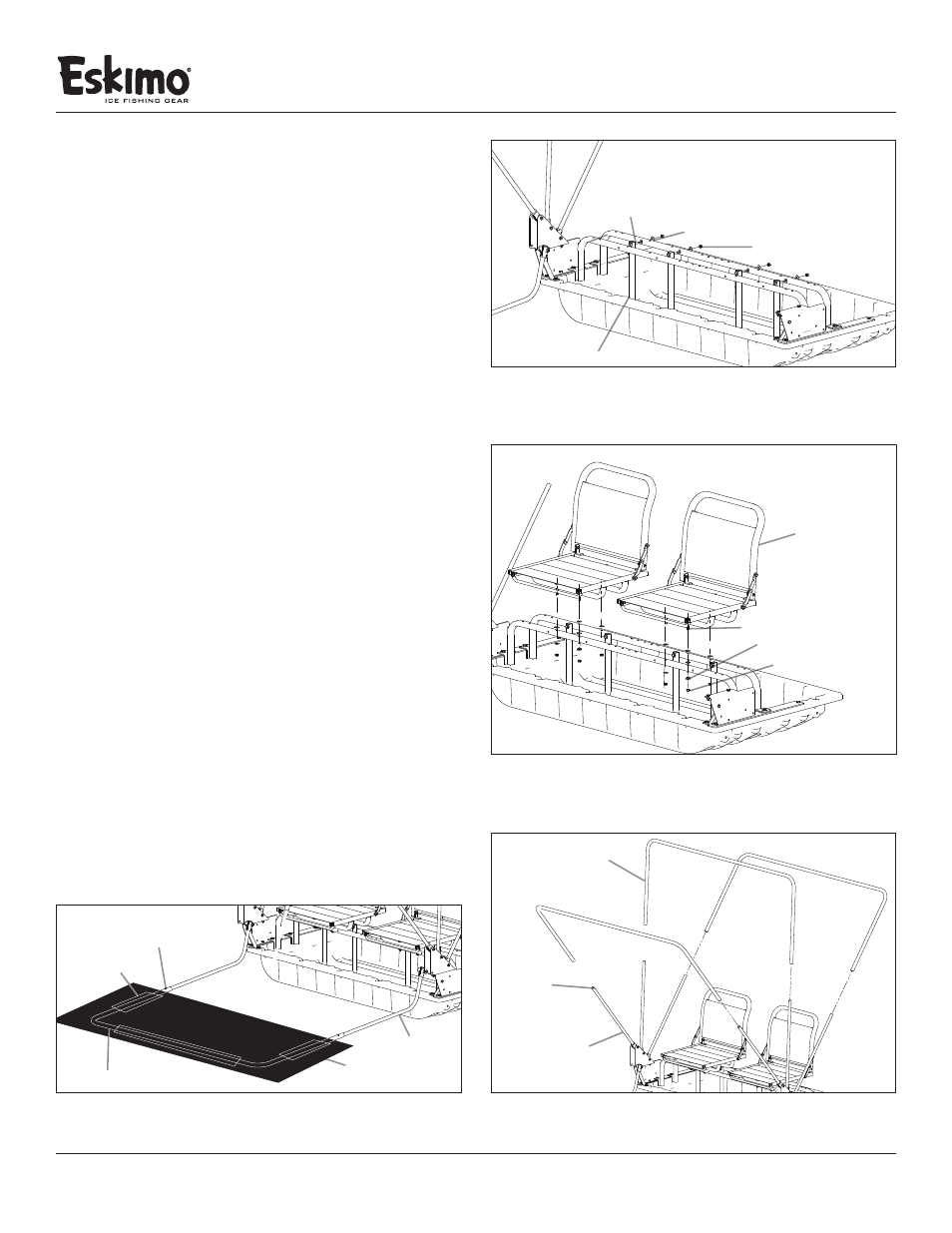
7. Attach the (2) vertical frame supports (11305) by locating the
correct holes in the back seat rail (11200) that are illustrated
in Figure 4. Using (4) ¼-20 x 2-1/4” bolts, (8) ¼” washers and
(4) ¼-20 nylock nuts. SEE FIGURE 4
8. Attach the (2) Seat Versa tops (15004) to the seat rails (11200)
using (4) ¼-20 x 2” bolts, (8) ¼” washers and (4) ¼-20 nylock
nuts. Repeat this step to install the other Seat Versa Top SEE
FIGURE 5
9. Tighten all hardware used to complete this portion of
assembly instructions.
SUPPORT POLE TO SLED INSTALLATION
10. Insert the 3 upright poles from each hinge (15551/15552) into
the (3) top cross brace poles (15554). Push the snap button
inward to allow the top cross brace to slide over the upright
hinge pole. Adjust the top cross brace assemblies on the hinge
to be in the transport position (lowest collapsed height). SEE
FIGURE 6
11. Unfold the skin and locate the Eskimo
®
logo near the zippered
door, which is in the front of the sled. With the outer part of
the shelter skin lying facing down, locate the (3) pole sleeves
on the bottom front, right side, and left side of the shelter
skin. Slide the bottom cross brace pole (15553) through the
(3) pole sleeves. SEE FIGURE 7 (Bottom of page)
12. Insert a hinge “J-Pole” from each hinge (15551/15552) into
the bottom cross brace pole (15553) with the skin attached
to the frame. Push snap button inward to allow the Lower
Cross Brace to slide over the (J-Poles) attached to the hinges.
FIGURE 4
¼-20 x 2-1/4” bolt
vertical frame support
¼” washer
¼-20 nylock nut
FIGURE 5
¼-20 x 2” bolt
Seat Versa top
¼” washer
¼-20 nylock nut
FIGURE 6
top cross brace pole
assembly hinge A
snap pin
FIGURE 7
J-pole
fabric sleeve
skin
bottom cross brace pole
snap button