Eskimo 15350 User Manual
Page 5
5
Check for parts online at
www.GetEskimo.com or call 800-345-6007 M-F 8-5 CDT
Operator’s Manual
ESKIMO
®
WIDE1
™
Inferno
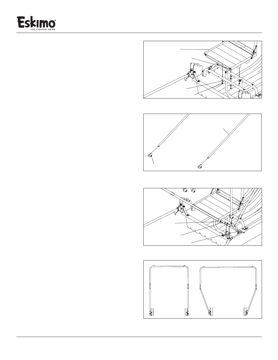
FIGURE 5
versa seat
¼” washer
¼-20 nylock nut
¼-20 x 1½” bolt
FIGURE 6
frame support pole
pole cap
FIGURE 7
support pole/
red pole cap assembly
¼-20 nylock nut
¼-20 x 2-1/4” pan head bolt
FIGURE 8
VERSA SEAT INSTALLATION
7. Locate the included Versa Seat (15004), (1) small parts bag
(15752) and the (1) swivel (15016). Attach the swivel (15016)
to the Versa Seat (15004) using (4) ¼-20 x 1½” bolts, (8) ¼”
washers and (4) ¼-20 nylock nuts. SEE FIGURE 4
8. To attach the seat/swivel assembly, from Step 7, to the seat
rail (14818), use the remaining hardware found in the small
parts bag (15752) -- (4) ¼-20 x 1½” bolts, (8) ¼” washers and
(4) ¼-20 nylock nuts. SEE FIGURE 5
FRAME ASSEMBLY
9. Locate the (6) pole caps (68060) and the (3) frame sup-
port poles (15519). Attach (1) pole cap to both end of
each support pole by pushing the cap over the pole
ends. Align the hole in the pole cap with the hole in
the support pole to ensure a correct assembly. SEE
FIGURE 6
Note: A rubber mallet may be helpful for this step.
10. Attach the (3) support pole/pole cap assemblies (15519/68060)
to the hinge assemblies (11652/11653) using (6) ¼-20 x
2-1/4” pan head bolts, and (6) ¼” washers. SEE FIGURE 7
Note: The bolt must go through all three parts--the frame
support pole, pole cap and hinge--to be assembled correctly.
DO NOT overtighten the bolts! The frame support poles need
to pivot up and down.
11. locate the female extension tube (15542) and the male
extension tube (15542), you may have to push the snap
button down to get the male tube started. With the
male and female extension tubes assembled, slide the
assembly into the “Travel Position” for the next step. SEE
FIGURE 8
travel position
in-use position