Assembly instructions – Eskimo 15350 User Manual
Page 4
Check for parts online at
www.GetEskimo.com or call 800-345-6007 M-F 8-5 CDT
4
Operator’s Manual
ESKIMO
®
WIDE1
™
Inferno
ASSEMBLY INSTRUCTIONS
Tools needed – (2) 7/16” wrenches, a Phillips head screwdriver,
rubber mallet (optional), and a cordless drill (optional).
Assembly Note: This ice shelter should be assembled in a
garage or basement setting due to the time and length of
assembly. Identify and familiarize yourself with all parts
and hardware before assembly. Allow 1-3 hours for assem-
bly.
Assembly Note: The use of a cordless drill with socket will
make assembly of your ice shelter much quicker. Be sure to
set the drill speed on low so you do not over tighten any nut
and bolt combination.
Assembly Note: If a tracking kit is purchased with the
shelter it should be mounted to the sled before assembly
of the ice shelter for convenience.
Important Assembly Tip: Do NOT fully tighten any nut and
bolt combination until instructed in later notes. This will
help hole alignment of all parts.
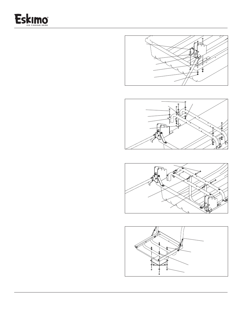
1. Attach the left hinge assembly (11652) to the shelter sled
using the spacer plate (11631), (2) ¼-20 x 3/4” bolts, (2) ¼”
washers and (2) ¼-20 nylock nuts. Repeat this step on the
opposite side using the right hinge assembly (11653). SEE
FIGURE 1
2. Attach the (2) hinge support straps (11203) to both hinge
assemblies (11652/11653) using (4) ¼-20 x 3/4” bolts,
(3) ¼” washers, and (4) ¼-20 nylock nuts. SEE FIGURE 1
Note: If the hole alignment is off or looks too far apart,
rotate the hinge support brace and try again. This part will
only bolt on one way.
3. Attach the (2) seat rails (15033) using (2) support shims
(11230), (4) ¼-20 x 1” bolts, (8) ¼” washers, and (4) ¼-20 nylock
nuts. The seat rail closest to the front of the sled will use the
last slotted hole on the spacer plate (11631) that was installed
in Step 1. The remaing seat rail (15033) will require the (2)
support shims (11230) to keep the height between the two
seat rails consistent. SEE FIGURE 2
4. Attach the (2) rail supports (15650) using (4) ¼-20 x
2” bolts, (8) ¼” washers, and (4) ¼-20 nylock nuts. SEE
FIGURE 2
5. Attach the (1) vertical frame support (11305) using (2) ¼-20
x 2” bolts, (4) ¼” washers, and (2) ¼-20 nylock nuts. SEE
FIGURE 3
6. Tighten all hardware used to complete this portion of
assembly instructions.
FIGURE 1
hinge support strap
spacer plate
¼” washer
¼-20 nylock nut
right hinge assembly
¼-20 x ¾” bolt
FIGURE 2
seat rail
¼” washer
¼-20 nylock nut
support shim
¼-20 x 1” bolt
¼-20 x 2” bolt
rail suppport
FIGURE 3
¼” washer
¼-20 nylock nut
vertical frame support
¼-20 x 2-1/4” bolt
SEAT FABRIC HIDDEN FOR ASSEMBLY CLARIETY
FIGURE 4
versa seat
¼” washer
¼-20 nylock nut
¼-20 x 1½” bolt
Note:
(SEAT FABRIC
HIDDEN FOR
ASSEMBLY
CLARIETY)