0 installation – ENMET Remote Alarm Module User Manual
Page 5
R
EMOTE
A
LARM
M
ODULE
ENMET Corporation
3
3.0 Installation
3.0 Installation
W
ARNING
:
This equipment is not for use in hazardous combustible atmospheres as defined by the national electrical code.
Use in such atmospheres may result in property damage, injury or death.
W
ARNING
:
Verify that the facility circuit breaker, which supplies power to the control unit and Alarm Module, is off
and tagged out before proceeding to connect the power leads. Failure to disconnect the power may cause
injury to yourself and damage to the instrument.
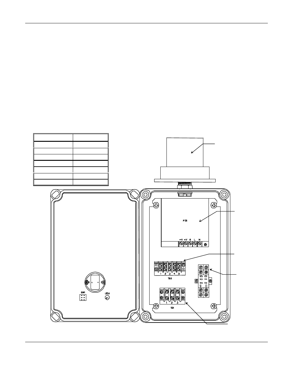
3.1 Wiring
The
AC
voltage is supplied to Terminal block (TB) 1. TB1-1
AC
high, TB1-2
AC
low, TB! -3
AC
ground. See figure 2.
Power for the dry relay contact located inside the control or sensor transmitter is supplied from TB2-4.
Power back from the control or sensor transmitter dry relay contact is connected to TB2-5. Consult equipment manual.
N
OTE
: The Remote Alarm Module is shipped with its rely contacts wired in a “fail Safe” mode. Movement of wires
connected to relay terminal TB2-4 and TB2-5 may be required to achieve the desired state.
Table 1: A
LARM
M
ODULE
Wiring
From
To
AC Line
TB1 – 1
AC Neutral
TB1 – 2
AC Ground
TB1 – 3
Transmitter Ground
TB2 – 2
Transmitter +24V
TB2 – 3
Transmitter Relay
TB2 – 4
Transmitter Relay
TB2 – 5
Figure 2: Alarm Module Interior View
Strobe
Terminal Block 1
Power Input
Terminal Block 2
Signal Input
Relay Block
Power
Supply