0 installation – ENMET IR-6000 User Manual
Page 6
IR-6000
Hydrocarbon Sensor/Transmitter
ENMET Corporation
4
3.0 Installation
W
ARNING
:
The user shall be made aware that if the equipment is used in a manner not specified by the
manufacturer, the protection provided by the equipment may be impaired.
N
OTE
:
The
IR-6000
transmitters are zeroed and have their response to the target gas verified prior to shipment. It is
recommended that following installation that a zero and sensor response test be preformed to insure that no damage to the
transmitter occurred during shipment and that proper installation has been preformed.
The first step in the installation process is to establish a mounting location for the
IR-6000
. Select a location that is typical of
the atmosphere to be monitored or close to the anticipated source of a dangerous gas.
It is very important that the
IR-6000
be properly located to enable it to provide maximum protection. The most effective
number and placement of sensors vary depending on the conditions of the application. When determining where to locate
sensors the following factors should be considered
What are the characteristics of the gas that is to be detected? Is it lighter or heavier than air? If it is lighter than air the
sensor should be placed above the potential gas leak. Place the sensor close to the floor for gases that are heavier than air or
for vapors resulting from flammable liquid spills. Note that air currents can cause a gas that is heavier than air to rise. In
addition, if the temperature of the gas is hotter than ambient air or mixed with gases that are lighter than air, it could also
rise.
How rapidly will the gas diffuse into the ambient air? Select a location for the sensor that is close to the anticipated source
of a gas leak.
Wind or ventilation characteristics of the immediate area must also be considered. Movement of air may cause gas to
accumulate more heavily in one area than in another. The detector should be placed in the areas where the most
concentrated accumulation of gas is anticipated. For outdoor applications with strong wind conditions, it may require the
sensors to be mounted closer together and on the down wind side, to the anticipated area of a gas leak. Also, take into
consideration for indoor applications, the fact that many ventilation systems do not operate continuously.
The sensor should be accessible for maintenance.
Excessive heat or vibration can cause premature failure of any electronic device and should be avoided if possible.
Follow all national and local installation codes and practices
.
The
IR-6000
has a ¾
″ NPT threaded connector for mounting the detector to a junction box.
A user-supplied junction box can be used providing it has the appropriate sized NPT conduit entries. The junction box must be
suitable for use in the application and location in which it is being installed. After the device has been installed, a zero
calibration is required. Refer to the Zero Calibration section of this manual.
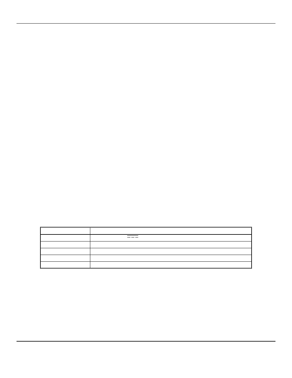
Table 1: Wiring connections
Wire
Description
Red wire:
18 to 32 V
DC
Black wire:
DC Common
Blue wire:
4–20 mA output
White wire:
Zero Calibration Data Wire
Earth Ground:
Male 10-32 Stud on IR-6000 cap, See Figure 1
W
IRE SIZING
:
Shielded cable is recommended. Wiring should be installed in medal conduit with no other cabling in the same conduit.
0 to 500 feet, recommended wire gauge size 16 AWG
501 to 1000 feet, recommended wire gauge size 14 AWG