ENMET EX-6175 User Manual
Page 6
EX-6175
ENMET Corporation
3
3.0 Installation of the EX-6175
C
AUTION
:
Area must be declassified during installation.
The
EX-6175
gas sensor/transmitter (S/T) is a 3-wire, 24
V
DC
4-20 mA S/T for the detection of combustible gas. The S/T is
meant to be used in conjunction with an appropriate power supply and controller. The
EX-6175
sensor/transmitter is in an
enclosure rated for use in area listed below:
Certificate Numbers
IECEx SIR08.0009X,Code EX d IIC
SIRA 08atex1031x, Code EX d IIC
Standards
IEC 60079-0 : 2004 (Edition 4)
EN 60079-0 : 2006
IEC 60079-1 : 2007-4 (Edition 6)
EN 60079-1 : 2007
Temperature Codes
T4 (Ta-20 to +60 deg C)
Zones
1 & 2
Equivalent Rating
Class I, Division 1, Group A, B, C & D
Appropriate wiring, conduit and fittings are required for proper installation in an explosion proof rated environment.
C
AUTION
:
Since the sensor/transmitter detects gas only at the sensor location, pay attention to the possible sources of gas, the
density of the gas, locations where the gas may be confined and locations where the gas may damage or injure
property or personnel, when choosing locations of sensor/transmitters.
Take into consideration environmental factors when deciding on S/T location. Avoid locations where the S/T may be damaged
by liquid immersion, excessive heat or other known hazards. Also, take precautions to insure condensation inside of the
conduit does not enter the S/T.
3.1 Mounting the EX-6175 Enclosure
Mount the enclosure, using the two mounting holes provided see Figure 2. Pay particular attention to the source and density of
the gas being detected when choosing the location. Mount the S/T near the ceiling for lighter than air gases /vapors and near
the floor for heavier then air gas/vapors. Contact
ENMET
if you have questions regarding your application.
C
AUTION
:
Before connecting S/T to controller remove the power source to controller. Failure to do so may cause damage to
sensitive components.
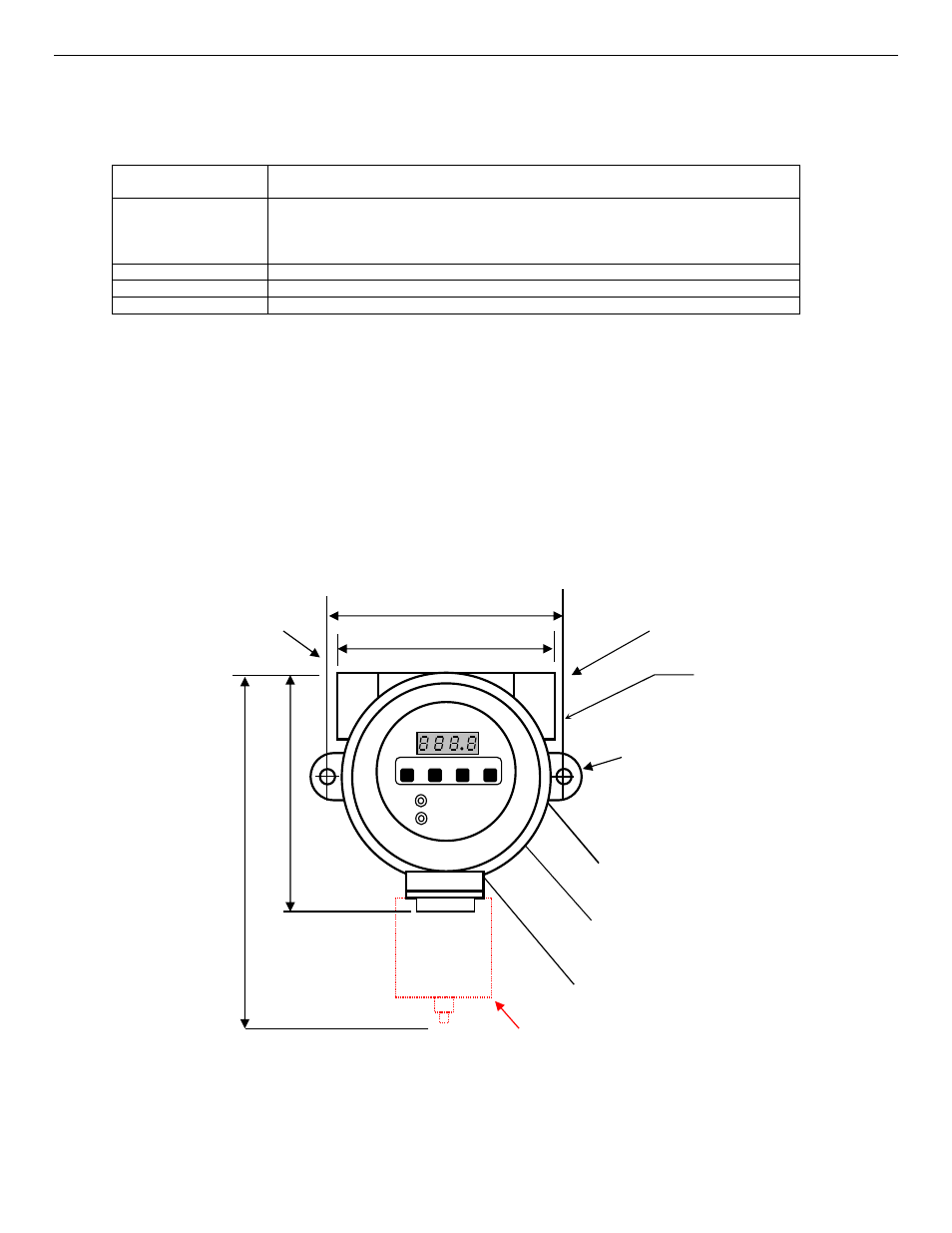
Figure 2: EX-6175 Mounting
Approximate Measurements in Inches (mm)
Maximum Depth = 5 Inches (127mm)
Optional
Conduit fitting
Typically: 3/4
″
NPT female
4.96 (126) Centers
4.53 (115)
5
.3
6
(
1
3
6
)
7
.4
8
(
1
9
0
)
2 x 0.27 (2 x 7) dia.
Mounting Holes
Optional Weatherguard
Inlet/Outlet
Port 1 of 2
Display
Menu Switches
Power & Alarm LEDs
Inlet/Outlet
Port 1 of 2
MENU UP DOWN ENTER