4 sensor replacement c, Figure 6: sensor replacement ma span – ENMET EX-5155 User Manual
Page 15
EX-5155-MOS
ENMET Corporation
13
Figure 5: EX-5155-MOS Maintenance Menu Flow chart
5.3 Heater Voltage Settings
Heater Voltages are necessary for MOS sensors. They are preset at the factory and should not require field adjustment. Do not
adjust these voltages unless specifically instructed to do so by
ENMET
Corporation Technical Support Staff.
C
AUTION
:
Improper adjustment of heater voltages can damage sensors voiding any warranties and also alter the operating
characteristics of the sensor in such a way that the
EX-5155-MOS
may not respond to it’s target gas.
5.4 Sensor Replacement
C
AUTION
:
Area must be declassified during sensor replacement.
Sensors should be replaced when they can no longer be calibrated. Replacement sensor part numbers are listed in Section 6.0
of this manual. If you do not know the proper part number for your sensor, be sure to have the
EX-5155-MOS
serial number
available when contacting your Distributor or
ENMET
Corporation Technical Support.
To replace a sensor, it is not necessary to open the transmitter housing.
Remove the set screw from sensor housing base.
Unscrew the sensor housing cover and remove spacer.
Note the orientation of spacer.
Unplug the sensor form PC Board.
Plug new sensor into PC Board and replace spacer.
Replace spacer with grooved edge toward sensor housing cover.
Reassemble the sensor housing.
After the new sensor has been installed, it is suggested to allow the sensor to stabilize for 24 hours.
A Factory calibration must be performed.
After entering the Maintenance menu, advance to the Zero menu. Then while viewing the Zero menu, hold the magnet over the
M
ENU
switch for 2-4 seconds.
After 2-4 seconds, an F will appear on the far right hand side of the display. The F indicates that the instrument is in Factory
mode.
Perform the calibration Zero and Span procedures as outlined in Section 5.2. Be sure that the F is present when selecting the
Zero and Span functions.
The Factory calibration sets a calibration window for future standard instrument calibrations.
Only perform a factory calibration when installing a new sensor!!
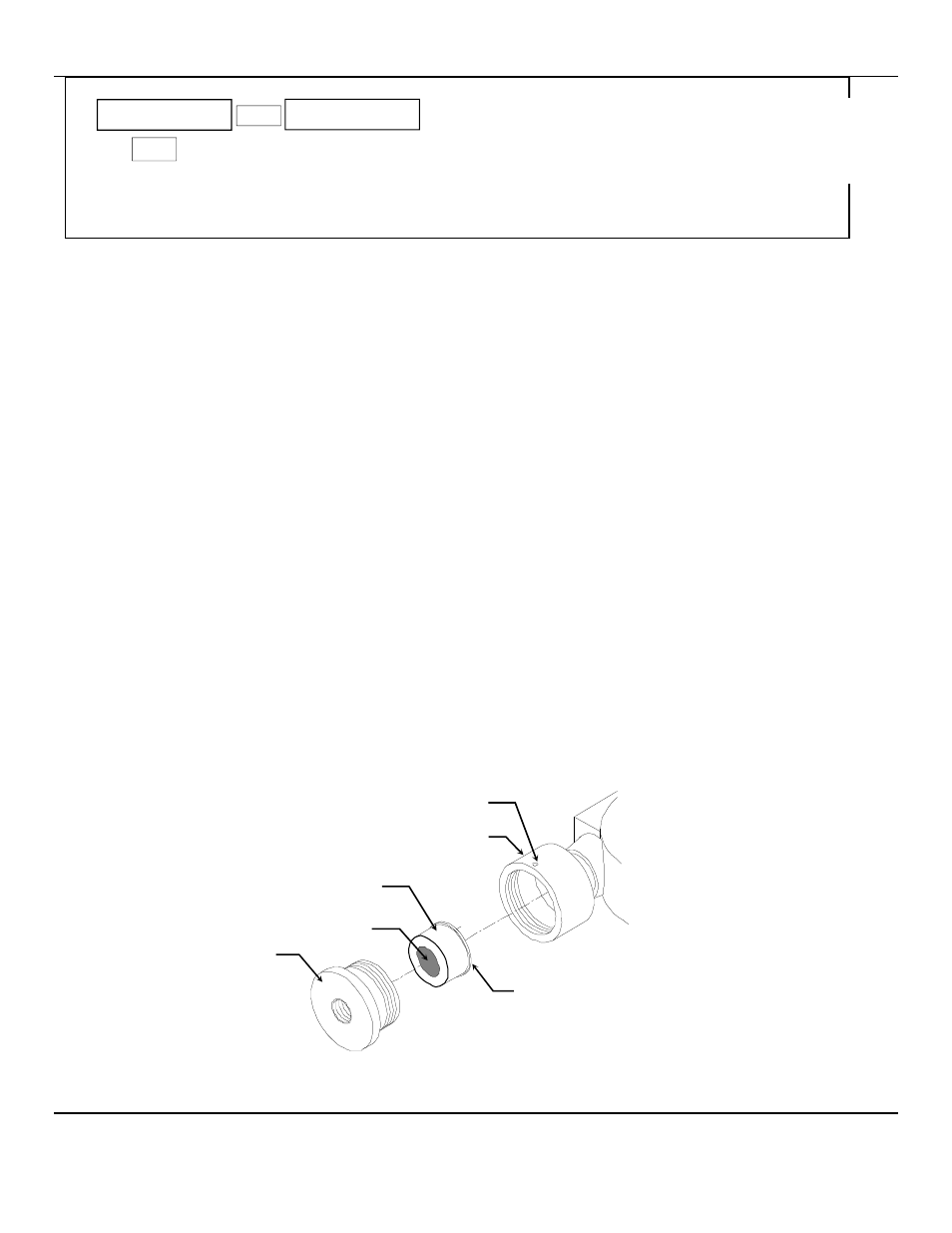
Figure 6: Sensor Replacement
mA Span
M
ENU
S
ELECT
100
To change mA Span set point:
Tap the M
ENU
switch until mA Span is displayed
Tap the S
ELECT
switch to display the set point
The M
ENU
switch changes digit indicated by underscore cursor
The S
ELECT
switch locks underscored digit and moves to next digit
To return to Normal Gas Display:
Tap M
ENU
switch until EXIT is displayed
Then tap S
ELECT
switch
Set Screw
(0.050 inch, 1.27mm Hex Key)
Sensor Housing Base
Sensor
Sensor Housing Cover
P C Board
Spacer
Note the orientation of spacer for replacement
Grooved edge of spacer toward Sensor Housing Cover