Users description of front panel control – Elenco Digital / Analog Trainer in Case User Manual
Page 3
-2-
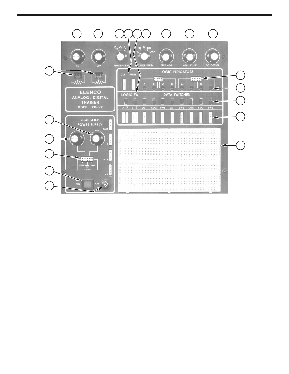
USERS DESCRIPTION OF FRONT PANEL CONTROL
1)
Fuse holder - Easy access for replacement of
1.25A 250V fuse.
2)
On-Off switch - Allows power to be applied to
all outputs. Switch will light when on.
3)
Power output terminals - This provides
30VAC center tapped at 15VAC - also provides
output terminal for positive and negative
variable voltages.
4)
Variable positive voltage control - Varies
positive voltage from 0 to 20V at indicated
output terminal.
5)
Variable negative voltage control - Varies
negative voltage from 0 to –20V at indicated
output connector pin.
6)
Output terminals
for 1k
Ω and 100kΩ
undedicated potentiometers.
7)
1k
Ω undedicated potentiometer.
8)
100k
Ω undedicated potentiometer.
9)
Waveform selection control, square, triangle
or sine generator waveforms.
10)
Output terminals for all functions as stated, 4
pins per block.
11)
Two logic switches - These are no bounce
logic switches. Give one signal state change
per movement of switch.
12)
Selects five ranges of frequencies from 10 to
100,000 hertz.
13)
Fine frequency control - allows easy selection
of desired function generator frequency.
14)
Amplitude control - Controls the function
generation output amplitude, 0-15Vpp.
15)
DC offset control - controls the DC level of the
generator output. DC may be varied +10 volts
from zero level.
16)
Input points for logic indicator LEDs. “A”
input corresponds with A lamp, etc.
17)
Logic indicators LEDs, total eight.
18)
Eight data switches - Output 5V or 0V
depending on position.
19)
Output terminals for all functions as stated, 4
pins per block.
20)
Two breadboards containing a total of 1,660
tie points including 6 independent bus lines.
1
2
3
4
5
6
7
8
13
14
15
16
17
18
19
20
12
11
10
9