Figure 9 – Elenco Digital / Analog Trainer in Case User Manual
Page 11
-10-
The XR-2206 is comprised of four functional blocks,
a voltage controlled oscillator (VCO), an analog
multiplier & sine shaper, a unity gain buffer amplifier
and a set of current switches.
The VCO actually produces an output frequency
proportional to an input current. Across pins 5 and
6, a timing capacitor, is switched on to give 5 different
ranges of frequencies via COARSE FREQ. switch.
On pin 7, the FINE FREQ. ADJ. variable resistor
controls the actual frequency output. These two
components form the RC time constants for the
oscillator frequency.
The VCO produces a squarewave signal. This
squarewave is sent to a shaper and converted into a
sine wave.
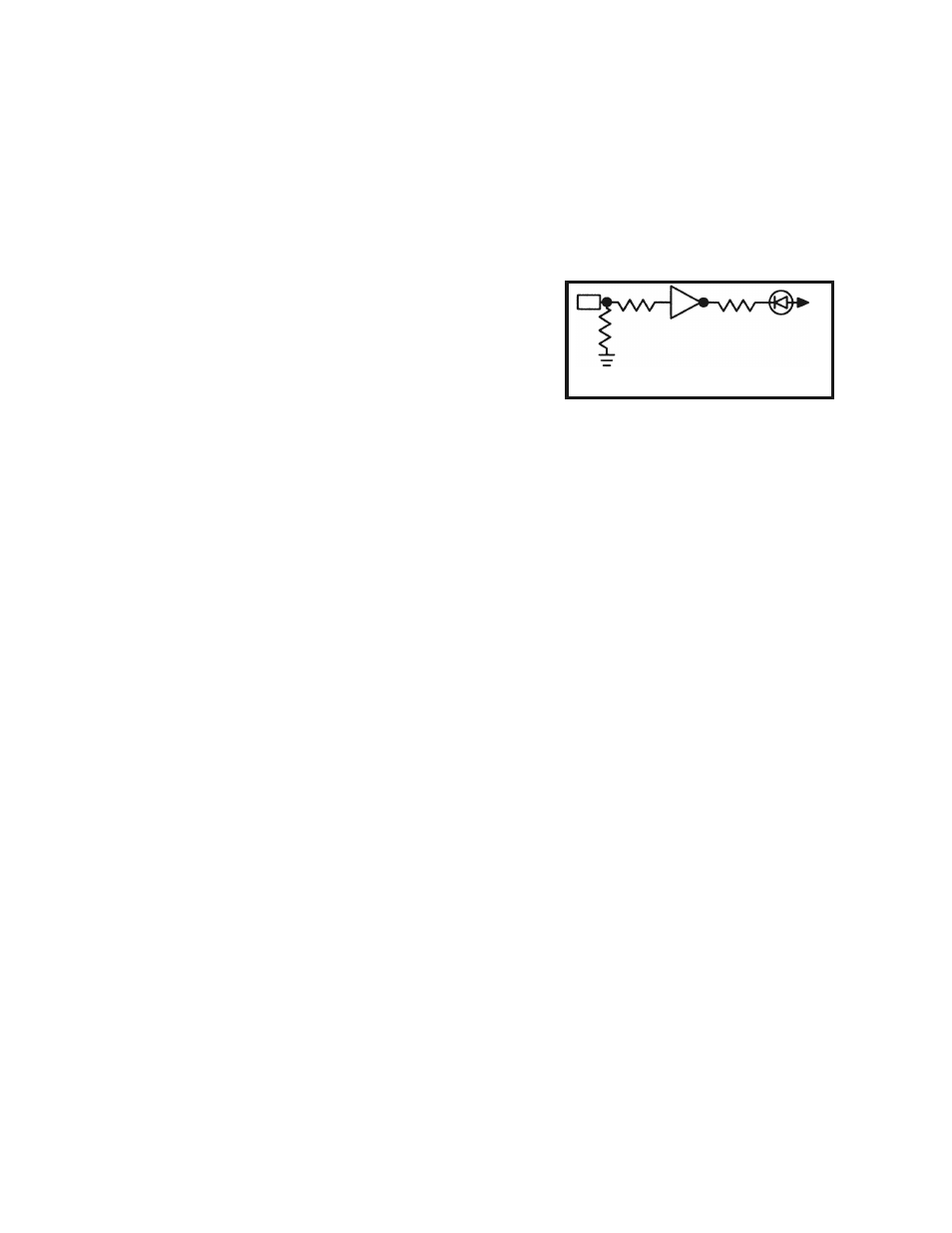
THE LOGIC INDICATORS
There are eight logic indicators. Figure 9 shows the
circuit. It consists of a 74HC04 IC. When the input
is over 2.8V, the output of the IC will be low, drawing
current through the LED indicator. The 120 ohm
resistor limits the current in the LED to about 30mA.
100k
Ω
100k
Ω
120
Ω
74HC04
LED
5V
Figure 9
- SEE AMFM108CK (56 pages)
- Computer Inteface for Snap Circuits® (60 pages)
- Capacitor Substitution Box (8 pages)
- Diode/Transistor Tester Kit (12 pages)
- Diode/Transistor Tester (8 pages)
- Electronic Component Kit (28 pages)
- 100kHz Function Generator in Kit Form (16 pages)
- 100kHz Function Generator (8 pages)
- Surface Mount Generator Kit (16 pages)
- 5MHz Function Generator (12 pages)
- 015V Power Supply Kit (8 pages)
- Resistor Substitution Box (8 pages)
- 3 3/4 Digit Cap./Ind./Logic (2 pages)
- Logic Probe Kit (12 pages)
- Logic Pulser Kit (12 pages)
- Compact Digital Multimeter (20 pages)
- Digital Multimeter (18 pages)
- 3 1/2 Digit Cap. / Trans. Kit (36 pages)
- Compact Multimeter (8 pages)
- Digital Mulitmeter Kit (20 pages)
- 23 Range 20k/V VOM in Kit Form (20 pages)
- 3 1/2 Digit Cap./ Freq./ Trans. w/ Grey Boot (8 pages)
- 3 1/2 Digit with Temperature (36 pages)
- 3 1/2 Digit Cap./ Trans./ Freq (4 pages)
- Digital Bench Multimeter (26 pages)
- MicroMaster ® Computer Training Kit (116 pages)
- 100MHz Scope (68 pages)
- Wide Band RF Generator (7 pages)
- Deluxe Solar Educational Kit (15 pages)
- Soldering Station (6 pages)
- Soldering Station (20 pages)
- Soldering Station (4 pages)
- Surface Mount Technology Kit (12 pages)
- Practical Soldering Project Kit (16 pages)
- DataCom Tester Kit (28 pages)
- MultiModular Cable Tester (4 pages)
- Tone Generator (4 pages)
- Telephone Line Analyzer Kit (16 pages)
- Digital / Analog Trainer Kit Version (52 pages)
- Deluxe Digital / Analog Trainer with Tools Kit Version (52 pages)
- Digital / Analog Trainer (12 pages)
- Deluxe Digital / Analog Trainer (16 pages)
- Variable Voltage Power Supply Kit (12 pages)
- Variable Voltage Power Supply (8 pages)