Assemble the following components to the pc board, Assemble components to the case and pc board – Elenco Telephone Line Analyzer Kit User Manual
Page 8
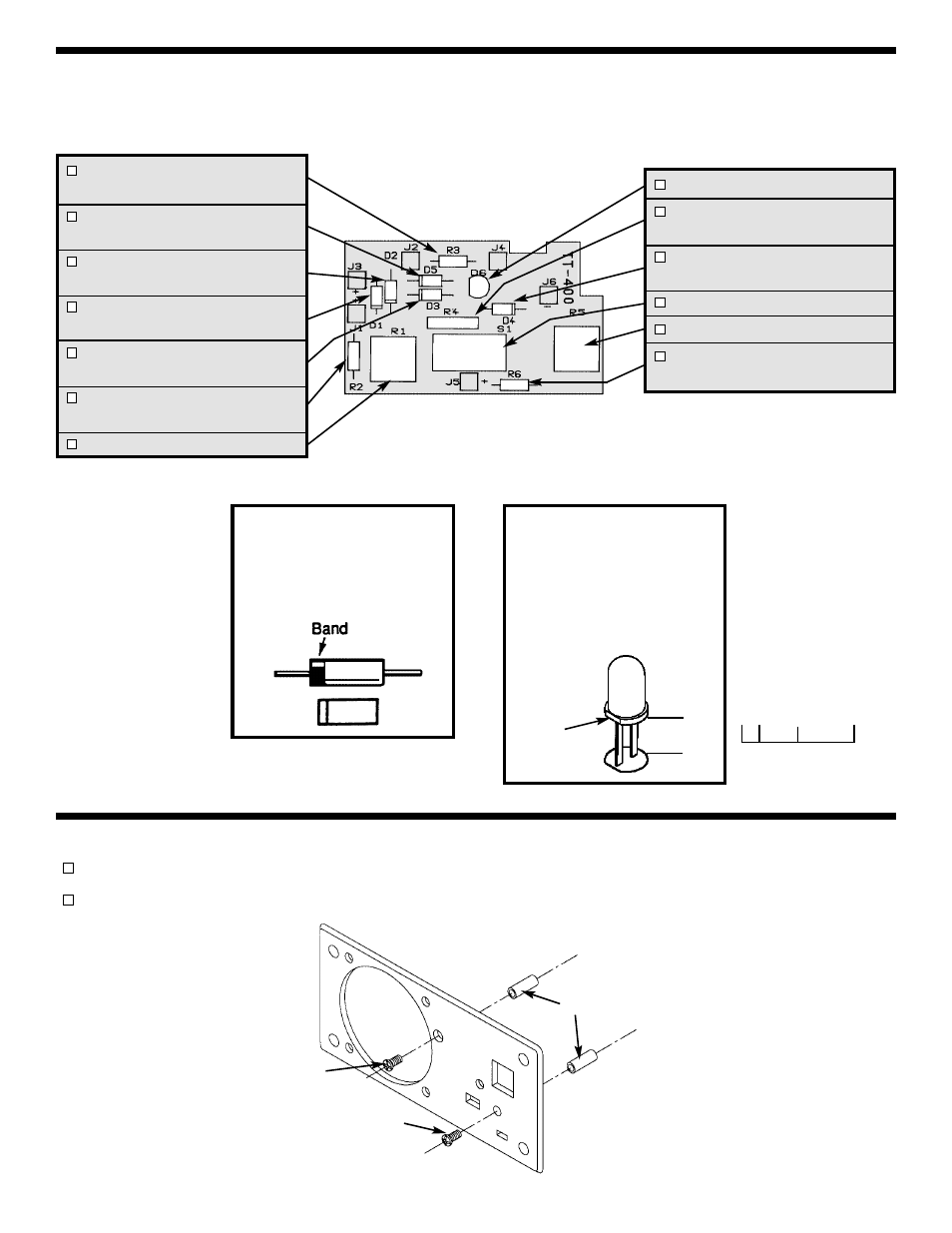
ASSEMBLE THE FOLLOWING COMPONENTS TO THE PC BOARD
In all of the following assembly steps, the components must be installed on the top legend side of the PC board.
The board is turned to solder the component leads on the foil side.
R3 - 15k
Ω
1/4W 5% Resistor
(brown-green-orange-gold)
D5 - 1N4004 Diode
(see Figure A)
D2 - 1N4004 Diode
(see Figure A)
D1 - 1N4004 Diode
(see Figure A)
D3 - 1N4004 Diode
(see Figure A)
R2 - 4.7k
Ω
1/4W 5% Resistor
(yellow-violet-red-gold)
R1 - 50k
Ω
Trim Pot
D6 - LED (see Figure B)
R4 - 200
Ω
1W 5% Resistor
(red-black-brown-gold)
D4 - 1N4004 Diode
(see Figure A)
S1 - Switch
R5 - 100k
Ω
Trim Pot
R6 - 100k
Ω
1/4W 5% Resistor
(brown-black-yellow-gold)
Figure A
Diodes have polarity. Mount
them with the band in the
correct direction, as shown on
the PC board.
Figure B
Mount the LED with a 5/32”
gap between the LED and the
PC board. The flat side of the
LED should be in the direction
shown on the PC board.
-7-
ASSEMBLE COMPONENTS TO THE CASE AND PC BOARD
Mount the spacer next to the meter hole from the front side with a 4-40 x 1/4” flat head screw (see Figure C).
Mount the other spacer with a 4-40 x 1/4” black screw (see Figure C).
Figure C
4-40 x 1/4” Black Screw
4-40 x 1/4” Flat Head Screw
Spacers
Flat
5/32”
5/32”
0
1”
1/2”