Telephone operation, The rotary dial telephone, Hook switch – Elenco Telephone Line Analyzer Kit User Manual
Page 3: Dialer, Figure 1, Figure 2, Figure 3
-2-
TELEPHONE OPERATION
The primary purpose of the telephone is to transmit
and receive voice signals allowing two people with
telephones to communicate with each other. To be
of practical value, the telephone must be connected
to a switching network capable of connecting each
telephone to many other telephones. To accomplish
this switching, each subscriber telephone is
connected to the telephone company’s Central
Office by two wires referred to as the local loop. A
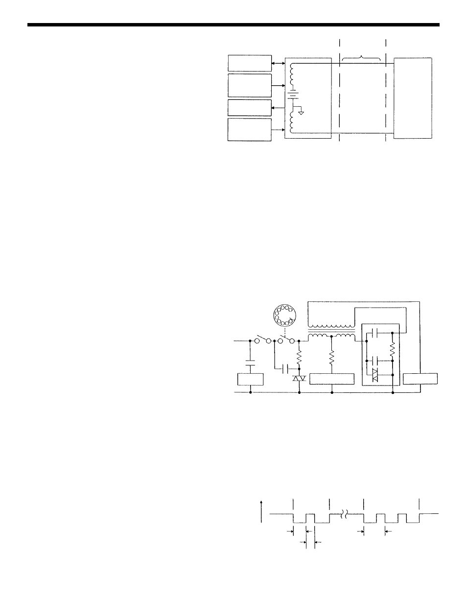
simplified diagram of this connection is shown in
Figure 1. The Tip and Ring designation of the + and
-- leads comes from the days of the manual
switchboard. The tip of the plug the operator used
to connect telephones carried the + lead and the
ring immediately behind the tip carried the -- lead.
When a subscriber wishes to place a call, they merely pick up the telephone and a small current flows in the
local loop. This current picks a relay in the Central Office indicating that service is being requested. When the
Central Office is ready to accept the number being called, a dial tone is sent to the calling telephone. The dial
pulses or tones then signal to the Central Office the number of the telephone being called. A path is then
established to that telephone. This path may be a simple wire connection to a telephone connected to the same
Central Office or it may go via wire, microwave link, or satellite to a telephone connected to a distant Central
Office. To signal the incoming call a ringing signal is placed on the local loop of the called telephone. The
ringing signal is a 90VAC 20Hz signal superimposed on the 48VDC present on the local loop. A ringing tone is
also sent to the calling telephone.
When the called party picks up the phone voice communication is
established.
THE ROTARY DIAL TELEPHONE
A simplified schematic diagram of the traditional rotary
dial telephone is shown in Figure 2. The major parts
of this telephone are explained below. In the newer
electronic type telephones, many of the bulky parts of
this telephone are replaced by transistors, integrated
circuits and piezoelectric buzzers.
HOOK SWITCH
When the hook switch is open (on hook), no current flows in the local loop. The 48VDC from the battery in the
Central Office appears on the tip and ring input to the telephone set. When the receiver is lifted, the hook switch
closes and a current of about 20 to 120mA flows in the local loop. The resistance of the local loop drops the
voltage of the telephone to about 6 volts. The current picks a relay in the Central Office which tells other
equipment there that service is being requested. When the Central Office is ready to accept the number being
called, a dial tone is sent to the calling telephone. The dial tone stops when the first digit is dialed.
DIALER
There are two types of dialers, pulse and tone.
Pulse Dialer
Pulse dialing is accomplished by the familiar rotary
dial shown in Figure 2. The dial is rotated to the
stop and then released.
A spring in the dialer
returns the dial to its null position. As the dialer
returns, the dial switch (S2) opens and closes at a
Figure 1
Central Office
Switch
Network
Ringing
Signal
Generator
Current
Relay
Control
Signal
Generators
Ring (--)
Tip (+)
48VDC
Local
Loop
Subscriber
Telephone
Figure 2
Balance
Network
Receiver
Transmitter
Ringer
S1
S2
C1
L1
L2
R2
R1
V1
L3
C2
C3
R3
V2
Figure 3
Loop
Current
Space
60mS
0
2
3
Pulse Period
100mS
Mark
40mS