Elenco Resistor Substitution Box User Manual
Page 6
-5-
r SW3 - PC Mount Switch
Mount SW3 in the place shown on the PC board.
Solder into place.
r Red Test Lead
r Black Test Lead
Cut off 1 1/2” of wire off of both the red and black
wires (SAVE them for later use). Strip 1/4” of
insulation off both ends of the 10 1/2” red and black
wires and insert them into the holes as marked on
the PC board. Solder into place. Tie a knot with
both wires 1 1/2” from the surface of the PC board
as shown in Figure 1. Pull the wires through the
hole in the cover. Slide the alligator boots onto the
wires. Solder the wires to the alligator clips. Then,
slide the boots onto the clips.
r SW1
r SW2
Bend the tab on the switches
down (see Figure 2). Attach the
two switches loosely to the front
panel with the 9mm nuts and
washers. Line up the holes of
the PC board with the switch
lugs, as shown in Figure 3. Be
sure that the board lays flat,
then solder the lugs into place.
Tighten down the 9mm nuts.
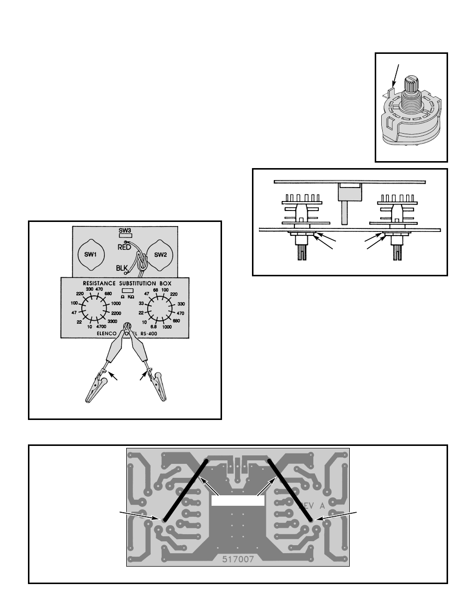
r Jumper wire from SW1
r Jumper wire from SW2
Strip 1/4” of insulation off of both ends of the 1 1/2”
red and black wires. Solder one end of the wire to the
wiper pin on the 12 position switches and the other to
the pad without a hole, as shown in Figure 4.
r Installation of Knobs if an Ohmmeter is Available
Place the knobs loosely on the switch posts. Push
the slide switch to the “
Ω” position. Connect an
ohmmeter to the output. Line up the pointer of the
knob with the value shown on your meter, then push
the knob onto the shaft. Push the slide switch to the
“K
Ω” position and repeat the same procedure.
Figure 4
SW1
SW2
Wiper Pin
Wiper Pin
Jumper Wires
Figure 3
9mm Nut
Washer
Cover
Figure 2
Bend Tab Over
PC Board
Figure 1
Bend Tabs
Over Wire