Project 7 blinking colors, Project 4 adjustable light, Project 5 row of lights – Elenco LED Fun User Manual
Page 2: Project 6 adjustable row of lights
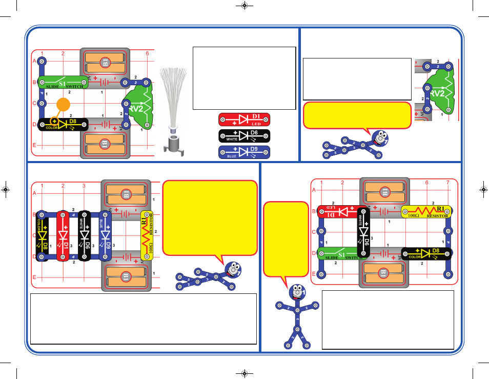
Project 7
Blinking Colors
Leave the swtich (S1) off at first; the white and color
LEDs (D6 & D8) are blinking. Now turn on the switch;
the red LED (D1) is blinking but the white LED is off.
If you swap the locations of the red and white LEDs,
then the red LED will be blinking and the white LED will
be off, and turning on the switch won’t change anything.
Try replacing any of the LEDs with the blue LED (D9),
or swapping any of them with the color LED.
Build the circuit as shown, and turn on the
slide switch (S1). Move the lever on the
adjustable resistor (RV2) to vary the
brightness of the color LED (D8). If
desired, place the fiber optic tree and
mounting base on the color LED. For best
effects, place the circuit in a dimly lit room.
Next, replace the color LED (D8) with the
red, white, or blue LEDs (D1, D6, & D9).
Project 4
Adjustable Light
+
If desired, place
fiber optic tree
& mounting base
on color LED
Project 5
Row of Lights
The switch (S1) isn’t used here, so this circuit will always be on. The red LED (D1) will be bright,
but the brightness of the other LEDs (D6, D8, & D9) may vary. If you remove the red LED from
the circuit then the others get brighter. For best effects, take the circuit into a dimly lit room.
Place the fiber optic tree on one LED if desired.
Now replace one of the battery holders (B1) with the switch (S1), and turn it on. The red LED is
bright, the blue & white LEDs may be dim or off, and the color LED may only be flashing red.
Now remove the red LED from the circuit and see if the others get brighter.
Use the project 5 circuit but replace the 100W
resistor (R1) with the adjustable resistor
(RV2), connected as shown. Move the lever
on RV2 around and compare the circuit to
project 5. Try using only two or three of the
LEDs at once.
Project 6
Adjustable Row of Lights
RV2 has higher resistance on all settings than
R1 did, which limits the flow of electricity much
more than in project 5. RV2 can be adjusted
from 200W to 10,000W.
When the red and
white LEDs are
connected
in
parallel (which
happens when S1
is on), the red
LED will dominate
because it turns
on more easily.
The blue LED will
perform similarly
to the white LED.
Red light is easier for LEDs to produce
than the other colors. When all the LEDs
are connected in parallel like they are
here, the red LED will dominate because
it turns on more easily. Resistor R1 limits
the flow of electricity from the batteries,
and the red LED takes most of it. The
other LEDs may not get enough
electricity, especially when there is only
one set of batteries. When electricity is
limited, the color LED can make red light
more easily than other colors.
SCP-11_021914.qxp_SCP-11_Instructions 3/7/14 10:40 AM Page 2