Assemble components to the pc board – Elenco Electronic Cricket User Manual
Page 6
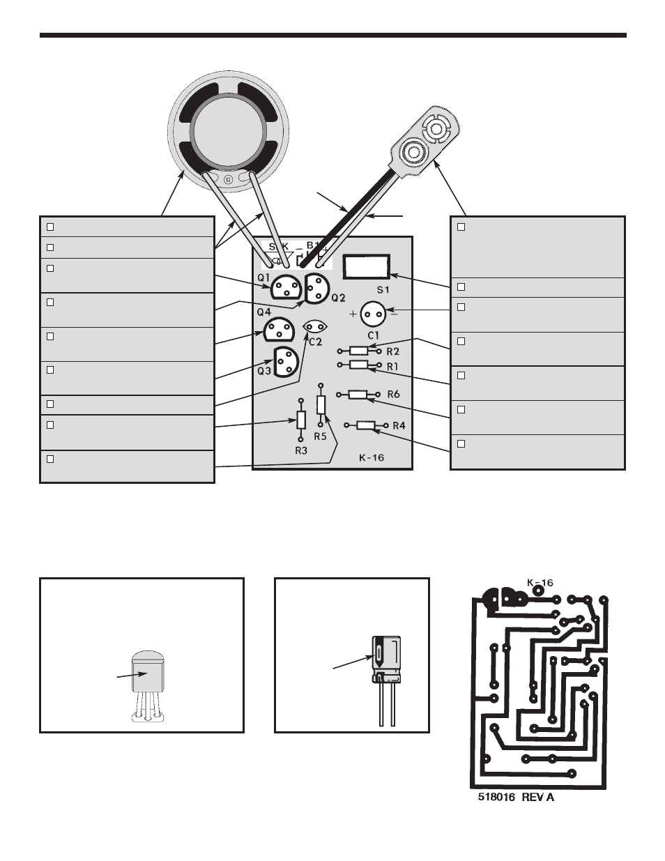
Figure A
Mount the transistor on the position shown. Make
sure that the flat side of the transistor agrees with
the flat side of the marking on the PC board.
Leave 1/4” between the transistor and the PC
board.
ASSEMBLE COMPONENTS TO THE PC BOARD
-5-
Figure B
Electrolytic capacitors have polarity.
Mount the capacitor with the positive
lead in the hole marked (+) on the PC
board.
Polarity
Marking
SPK - Speaker
4” Speaker Wires
Q1 - 2N3904 Transistor
(see Figure A)
Q2 - 2N3906 Transistor
(see Figure A)
Q4 - 2N3906 Transistor
(see Figure A)
Q3 - 2N3904 Transistor
(see Figure A)
C2 - .01
m
F (103) Discap
R3 - 1.5k
W
5% 1/4W Resistor
(brown-green-red-gold)
R5 - 1k
W
5% 1/4W Resistor
(brown-black-red-gold)
B1 - Battery Snap - Insert the
black wire into the negative (–)
hole and the red wire into the
positive (+) hole.
SW1 - Slide Switch
C1 - 100
m
F Electrolytic Cap.
(see Figure B)
R2 - 22k
W
5% 1/4W Resistor
(red-red-orange-gold)
R1 - 1M
W
5% 1/4W Resistor
(brown-black-green-gold)
R6 - 360
W
5% 1/4W Resistor
(orange-blue-brown-gold)
R4 - 100k
W
5% 1/4W Resistor
(brown-black-yellow-gold)
Foil Side of PC Board
Flat
(–)
(+)
Red
Black