Circuit operation, Oscillator circuit, Audio amplifier – Elenco Digital Bird User Manual
Page 4: The r/c circuit, Figure 1, Figure 2, Figure 3
-3-
CIRCUIT OPERATION
The Digital Bird uses four digital NAND gates to
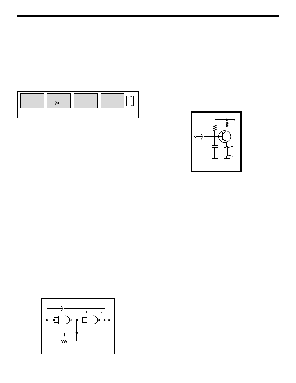
produce the birdy sounds. It consists of four
individual circuits: two oscillators, an audio amplifier
and an R/C network as shown in the block diagram
in Figure 1. The first oscillator produces a square
wave signal whose frequency can be varied by
adjusting a variable resistor. The output of the first
oscillator is modified by passing it through a high
pass R/C network. The resulting sound is fed to an
audio amplifier which drives a speaker.
What makes the Digital Bird so exciting is the fact
that three circuits have variable controls. Thus, the
sound output can be adjusted over a wide range to
give an unusually large variety of audio sounds in
the “birdy frequency” spectrum.
Oscillator Circuit
The circuit of the first oscillator is shown in Figure 2.
Two NAND gates are wired as inverters. This means
that when the input is high, the output goes low. To
make a circuit oscillate, we need positive feedback.
This is achieved by adding capacitor C1. The output
of inverter G1 is fed back to the input of G2 in the
same phase to build-up the oscillations. Capacitor
C1 and resistor R1 form an R/C network, and this
network determines the frequency of oscillation.
Since resistor R1 can be varied, the frequency of
oscillation can be varied. The resulting output
produces a square wave whose frequency is varied
by adjusting resistor R1. The operation of the
second oscillator is the same as the first oscillator
except that the value of capacitor C1 is 1,000 times
smaller. This produces a frequency much higher
than the first oscillator. The input of the second
oscillator is modulated with the output of the first
oscillator to produce the weird sounds of the Digital
Bird.
Audio Amplifier
Figure 3 shows the circuit of the audio amplifier
used in the Digital Bird. This transistor circuit is
known as an emitter follower. The output of the
second oscillator is fed to the input base of the
amplifier via capacitor C4. In a transistor, the base-
emitter current is amplified in the collector-emitter
circuit, usually about 100 times. Therefore, the
speaker will produce a much amplified sound. The
emitter of transistor Q1 supplies the power to the
speaker. Resistor R5 is added to protect the
transistor from excessive current. Resistor R4 is
added to bias the transistor on.
The R/C Circuit
There is an R/C network in both of the oscillators in
the Digital Bird. These R/C circuits control the
frequency of oscillation. The output of the first
oscillator is a low frequency square wave. This
square wave is fed to a third R/C network which
drives the second oscillator. Resistor R2 and
capacitor C2 make up this R/C network. Its function
is to alter the square wave before it is mixed with the
second oscillator. The resulting special effects
voltages are fed to the audio amplifier stage through
coupling capacitor C4. The function is to block the
DC output of G3 while passing the desired AC
pulse.
Note that the waveform of each of the three circuits,
the two oscillators and the connecting R/C circuit,
can be altered by varying potentiometer R1, R2,
and R3. The results are the interesting special effect
sounds which provide hours of entertainment.
First
oscillator
variable
RC circuit
Second
oscillator
variable
Audio amp
SPK
Figure 1
LO
R1
Positive feedback
G2
G1
LO
HI
C1
Output
Figure 2
SPK
Q1
C5
C4
R4
R5
9V
Figure 3