Warning, Ardisam – EarthQuake W2265V User Manual
Page 5
ARDISAM
.com
Earthquake, Division of Ardisam, Inc.
Page 5
800-345-6007
ASSEMBLY INSTRUCTIONS AND PARTS ExPLOSIONS
Log Splitter Models
SET-UP INSTRUCTIONS:
Tools needed - (2) 9/16” wrenches, (2) 1/2” wrenches, (2) 3/4” wrenches, (1)
flat screwdriver, (1) pair of pliers, (1) 10” adjustable wrench, (1) pipe wrench
and (1) rubber mallet.
NOTE: EACH LOG SPLITTER WAS PARTIALLY ASSEMBLED AT THE
fACTORY. REfER TO THE PARTS ExPLOSIONS fOR DETAILED AS-
SEMBLY.
IMPORTANT ASSEMBLY TIP: ALL THREADED HOSE CONNECTIONS
NEED TO BE WRAPPED WITH TEfLON TAPE SUPPLIED IN THE PARTS
BAG BEfORE CONNECTING HOSES.
1. Remove all components from the crate. Inspect each piece for shipping
damage. If any part is damaged, contact your dealer.
2. Attach the wheels to each side of the hydraulic cage by sliding the end of
the spindle into the tubes at the bottom of the cage. Make sure that the
holes line up as you insert the spindle. Secure in place with two 5/16-18
x 2-1/4” bolts and two 5/16-18 bi-way locknuts. Avoid damage to bearing
protectors while tapping in place with a rubber mallet.
NOTE: The rest of the assembly is easier done with at least two
people.
3. Next, attach kickstand to tongue using one 3/8-16 x 3” bolt, two 3/8” flat
washers, one 3/8-16 bi-way locknut, one 3/8” x 2-3/4” pin and one hair
clip. Attach the kickstand to the tongue so that it will support the weight
of the log splitter as you assemble the rest of the pieces.
DO NOT OVER
TIGHTEN - MUST SWING fREELY.
4. Next, attach the tongue to the hydraulic cage using two 3/8-16 x 3” bolts
and two 3/8-16 bi-way locknuts. Attach travel lock assembly to the tongue
using two 3/8-16 x 3” bolts and two 3/8-16 bi-way locknuts. Position of pin
should be toward operator’s side.
NOTE: At least two people are required to lift and assemble the
beam to the hydraulic cage. To avoid injury, always lift with your
legs and not your back.
5. Remove the beam and stand it upright on the foot as it would be in use.
Roll the hydraulic power pack into position and rotate the hydraulic power
pack with the tongue until the holes line up to insert the 5/8” x 4” pivot
pin. Insert a cotter pin into hole in pin and bend with pliers to secure.
SEE
PARTS ExPLOSION ON PAGES 8 & 14 fOR MORE DETAIL.
6. Rotate the beam until it is horizontal. Install the stripper bars facing up-
ward using four 1/2-13 x 1” bolts and four 1/2-13 bi-way locknuts. Install
the engine guard using two 1/4” x 2-1/4” safety snap pins and two 1/4-20
x 1-3/4” bolts with two 1/4-20 nyloc nuts.
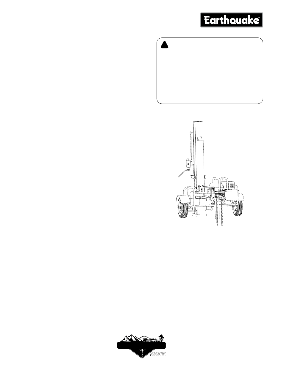
LOG SPLITTER IN VERTICAL POSITION
WARNING
!
READ AND UNDERSTAND ALL ASSEMBLY,
SAfETY, & MAINTENANCE INSTRUCTIONS PRO-
VIDED BEfORE EACH USE.
BECOME fAMILIAR WITH YOUR LOG SPLITTER
fOR YOUR OWN SAfETY. fAILURE TO DO SO
MAY CAUSE SERIOUS INJURY AND/OR DEATH.
DO NOT ALLOW ANYONE TO OPERATE YOUR
LOG SPLITTER WHO HAS NOT READ THIS MAN-
UAL. READ EACH STEP COMPLETELY BEfORE
PROCEEDING.