Connection to the ports, Hdmi, Rgb 1 – Dukane Projector 9136 User Manual
Page 3: Rgb out, At rgb signal, Rgb 2(g/y, b/c, H, v), Pin signal pin signal pin signal, Ac b d
3
D
HDMI
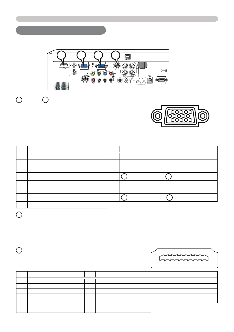
• Type :Digital audio/video connector
• Audio signal : Linear PCM (Sampling rate; 32/44.1/48 kHz)
Connection to the ports
Connection to the ports
A
RGB 1,
B
RGB OUT
D-sub 15pin mini shrink jack
• Video signal: RGB separate, Analog, 0.7Vp-p,
75Ω terminated (positive)
• H/V. sync. signal: TTL level (positive/negative)
• Composite sync. signal: TTL level
At RGB signal
Pin
Signal
Pin
Signal
1
Video Red
9
(No connection)
2
Video Green
10 Ground
3
Video Blue
11 (No connection)
4
(No connection)
12
A : SDA (DDC data), B : (No connection)
5
Ground
13 H. sync / Composite sync.
6
Ground Red
14 V. sync.
7
Ground Green
15
A : SCL (DDC clock), B : (No connection)
8
Ground Blue
Connection to the ports
10
9
8
7
6
5
4
3
2
1
15
14
13
12
11
LAN
VIDEO
CONTROL
AUDIO IN1
AUDIO IN2
AUDIO OUT
RGB
OUT
RGB1
RGB2
HDMI
R L R L
AUDIO IN3
AUDIO IN4
C
B
/P
B
Y
C
R
/P
R
B/C
B
/P
B
R/C
R
/P
R
G/Y
H
V
USB
REMOTE
CONTROL
S-VIDEO
A
C
B
D
Pin
Signal
Pin
Signal
Pin
Signal
1
T.M.D.S. Data2 +
8
T.M.D.S. Data0 Shield
15 SCL
2
T.M.D.S. Data2 Shield
9
T.M.D.S. Data0 -
16 SDA
3
T.M.D.S. Data2 -
10 T.M.D.S. Clock +
17 DDC/CEC Ground
4
T.M.D.S. Data1 +
11 T.M.D.S. Clock Shield
18 +5V Power
5
T.M.D.S. Data1 Shield
12 T.M.D.S. Clock -
19 Hot Plug Detect
6
T.M.D.S. Data1 -
13 CEC
7
T.M.D.S. Data0 +
14 Reserved(N.C. on device)
C
RGB 2(G/Y, B/C
B
/P
B
, R/C
R
/P
R
, H, V)
• BNC jack x 5
• Video : Analog 0.7Vp-p, 75Ω terminator
• H/V, sync, : TTL level (positive/negative)
• Composite sync, : TTL level
19 17 15 13 11 9 7 5 3 1
18 16 14 12 10 8 6 4 2