Display Devices Heavy Duty Projector Mount User Manual
Page 2
2
6/24/05
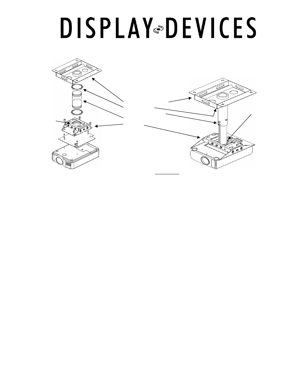
Pole Mount for Drop Tile Ceiling Mount
Ensure the ceiling structure is capable of holding at least four times the combined weight of the mount, pole
and projector. This is a minimum requirement; follow any local or state codes that apply to your specific area.
If you are mounting the PCM in a facility with a drop tile ceiling, your system should include a PLMT-T Top Pan
and a threaded 2” diameter pole. Display Devices Inc offers adjustable poles in 1-2 ft, 2-4 ft and 3-6 ft. lengths
as well as fixed pole cut to your specified length.
1. Mount PLMT-T Top Pan (1) to structural ceiling. If appropriate points do not exist, span beams with structural
channel and attach Top Pan to channel. Use 3/8” or 1/2” hardware.
2. Screw Lock Ring (2) onto threaded pole (4). If using a Display Devices Inc PLMT-Adjustable pole (3), extend
to full length. Screw threaded pole into PLMT-T Top Pan – tighten Lock Ring to prevent the pole from
turning. Screw another Lock Ring onto the bottom of the pole.
3. Determine the location where the pole will protrude through the ceiling tile. Carefully cut a hole in the ceiling
tile for the pole. Position the tile within the ceiling grid. Depending upon your ceiling, the tile may have to be
positioned within the grid prior to inserting the Pole into the PLMT-T. Adjust vertical elevation if using an
adjustable pole, tighten hardware, drill a hole with included bit and install set screw.
4. If the PCM has an interface plate, attach it to the projector with included hardware. If the PCM does not
provide an interface plate, attach the PCM directly to the projector.
5. Thread the PCM onto the pole turning in a clockwise manner – hand tighten. Tighten the lower Lock Ring
with a large wrench or tap with a screwdriver on the notches.
6. Route power and signal cables through the Top Pan then down the center of the pole exiting through the
PCM mount. Attach power and signal cables to the projector, turn projector on.
7. Loosen tilt adjustment screws and level the projected image to the screen. Tighten screws when a level
image is achieved.
8.
Loosen pitch adjustment screws and adjust the pitch angle of the projector. Tighten screws when at desired
projection position.
1 - PLMT-T Top Pan
2 - Lock Ring
3 - Adjustable Pole
4 - Fixed Pole
5 - PCM
2
2