Outer bezel assembly – Da-Lite UTB Contour User Manual
Page 4
4
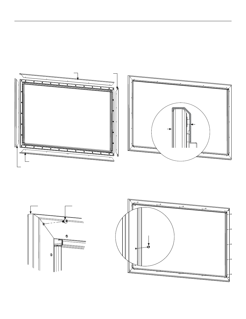
1. Position outer bezel pieces on all sides (Figure 3a). Gently lift and
slide each outer bezel piece around the inner frame and viewing
surface assembly (Figure 3b).
2. Align corners and insert one 8–32 x 3/8" screw in each corner to
attach the outer bezel onto the inner frame assembly (Figure 4).
Outer Bezel Assembly
(4) 8–32 x 3/8"
Machine Screws
Side View of Screen
with Bezel in Place
Bezel
Viewing
Surface
Align
Corners
Figure 3b
Figure 3a
Figure 4
Figure 5
Top Outer Bezel
Bottom Outer Bezel
Side Outer Bezel
Side Outer Bezel
#10 x 3/8"
Black Screws
3. Secure the outer bezel to the inner frame by inserting the #10 x
3/8" black screws into each of the large holes on all four sides of
the screen (Figure 5).
Note: The long outer bezel side with (2) or (4) small holes will be
the bottom of the screen. Do not insert screws in these holes as
they will be needed for the next step.