Operation and typical wiring diagrams, Jumper placement, Figure 2 figure 3 – AZEL i-Link SERIES ZONE CONTROLS (CIRCULATOR PUMP SWITCHING RELAYS ) FOR HYDRONIC / RADIANT FLOOR HEATING SYSTEMS User Manual
Page 3
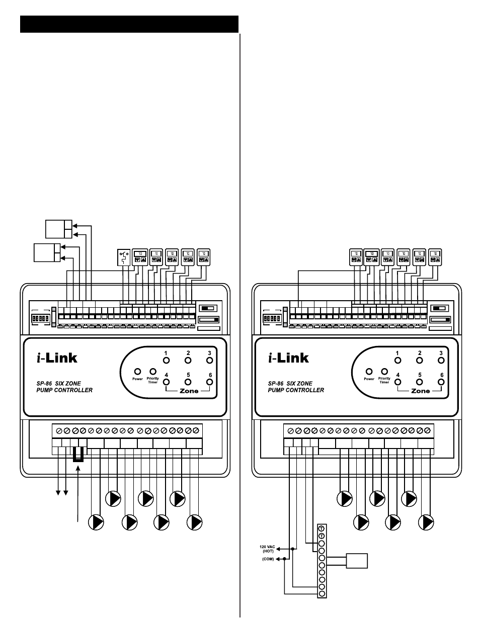
OPERATION AND TYPICAL WIRING DIAGRAMS
When zone thermostat calls for heat, the appropriate
circulator is actuated and the isolated end switch X-X will
start the boiler.
system
circulator is actuated if it is installed.
JUMPER PLACEMENT
The jumper (factory installed) should be placed between
terminal ZC and ZR. Connect isolated end switch X-X to
T-T terminals on boiler control.
COLD START (LOW THERMAL MASS) BOILER
APPLICATION
OPERATION
When zone 1 thermostat calls for heat,
end switch X1-X1 is also energized. In additon, a
TANKLESS COIL (HIGH THERMAL MASS)
BOILER APPLICATION
OPERATION
When zone thermostat calls for heat, the appropriate
circulator is actuated and the boiler is started. If the
boiler temperature drops below the low limit, all
circulators will cease until the boiler temperature is
increased above the low limit.
JUMPER PLACEMENT
Remove the factory installed jumper between terminals
ZC and ZR.
Connect terminal ZC to ZC terminal on boiler (aquastat)
control.
Connect terminal ZR to ZR terminal on boiler (aquastat)
control.
ON
ZONE 1 PRIORITY
OFF
MASTER SLAVE
ZONE EXPANSION
OUTPUT
T1
T1 T2 T2 T3 T3 T4 T4 T5 T5 T6 T6
1
2 3 4
C
24
VAC
R W R W R W R W R W R W
THERMOSTATS
ZC ZR
N L
120 Vac
120 VOLT CIRCULATORS
SYS PMP ZONE 1 ZONE 2 ZONE 3 ZONE 4 ZONE 5 ZONE 6
N L N L N L N L N L N L N L
Factory Installed
Jumper
System
Circulator
(Optional)
Zone 2
Circulator
Zone 4
Circulator
Zone 6
Circulator
Zone 1
DHW
Circulator
Zone 3
Circulator
Zone 5
Circulator
120 VAC
(HOT)
(COM)
Boiler/
Burner
Control
T
T
THERMOSTATS
(eg. Azel Tech, D-135E)
AQUASTAT ON INDIRECT/
DOMESTIC HOT WATER
(DHW) HEATER
COM
R W
3 WIRE
THERMOSTAT
Honeywell
L8148
MANUAL
PRIORITY OVERRIDE
ON
OFF
Zone
2 3 4 5 6
X
X
X1 X1
ISOLATED
END SWITCH
ZONE 1
TIMER
TT on Boiler with
DHW TT Terminals
Boiler
Control
T
T
DHW
ON
ZONE 1 PRIORITY
OFF
MASTER SLAVE
ZONE EXPANSION
OUTPUT
T1
T1 T2 T2 T3 T3 T4 T4 T5 T5 T6 T6
1
2 3 4
C
24
VAC
R W R W R W R W R W R W
THERMOSTATS
ZC ZR
N L
120 Vac
120 VOLT CIRCULATORS
SYS PMP ZONE 1 ZONE 2 ZONE 3 ZONE 4 ZONE 5 ZONE 6
N L N L N L N L N L N L N L
Zone 2
Circulator
Zone 4
Circulator
Zone 6
Circulator
Zone 1
DHW
Circulator
Zone 3
Circulator
Zone 5
Circulator
THERMOSTATS
(eg. Azel Tech, D-135E)
COM
R W
3 WIRE
THERMOSTAT
MANUAL
PRIORITY OVERRIDE
ON
OFF
Zone
2 3 4 5 6
X
X
X1 X1
ISOLATED
END SWITCH
ZONE 1
TIMER
BURNER
ZC
ZR
C1
C2
1
B1
B2
2
Honeywell L8124A or C
Figure 2
Figure 3