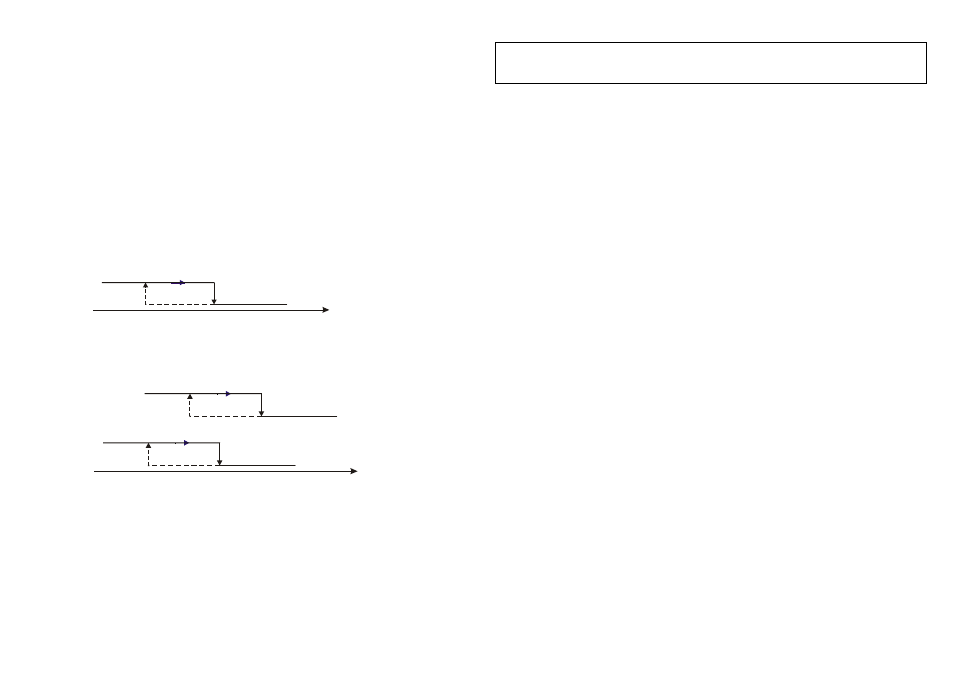
Fig. 2 - example two stage outputs dst-922 – AZEL SINGLE STAGE AND TWO STAGE DIGITAL SETPOINT TEMPERATURE CONTROL: DST-922 User Manual
Page 2
2.00 HOW THE DEVICE WORKS (overview)
The DST-900 is a thermostat, it has one output relay and it switches on when the temperature goes above or below (see “act”) the Set point value.
DST-902 is the same as DST-900 except that it has two output relays: both relay will switch on and off at the same time.
The DST-922 is a two independent outputs, one related to the main set point and the other to the second set point. Both outputs can be driven
according to the temperature of only one probe, the main probe – fig. 2.
The DST-900/DST-922 can perform also defrost cycles. Every “dpt” hours it will switch off both outputs K1 and K2 for “ddt” minutes.
2.10
DST900
- One stage with one probe controller (fig. 1 - supposed act=1):
K1 - Heater START temperature: temp Probe
≤ SEt - HyS;
K1 - Heater STOP temperature: temp Probe
>
SEt .
To avoid any damages it is possible to set an anticycling time against OFF – ON cycles (see “acy” parameters).
K1 - Cooler START temperature: temp Probe reaches(and greater than) SEt + HyS; K1 - Heater STOP temperature: temp Probe
<
SEt .
To avoid any damages it is possible to set an anticycling time against OFF – ON cycles (see “acy” parameters).
2.20
DST922 -
Two independent stages with one probe controller (fig. 2 - supposed act=1 and ac2=1):
K1 - Heater START temperature: temp Probe
≤ SEt - HyS;
K1 - Heater STOP temperature: temp Probe
>
SEt .
K2 - Heater START temperature: temp Probe
≤ St2 – Hy2;
K2 - Heater STOP temperature: temp Probe
>
St2 .
The cooling for DST-922 operates in a similar manner as DST-900.
To avoid any damages it is possible to set an anticycling time against OFF – ON cycles (see “acy” and “dl2” parameters).
2.30 Fault tolerance:
In case of probe failure the DST-900/DST-902/DST-922 controllers display a message PF1 and switch off the output K1 (as per table 7) .
4.00 HOW TO DISPLAY AND ADJUST THE MAIN SET POINT
Note: The internal mathematic calculation of the thermostat works in °C. When adjusting the temperature with temperature display unit set as °F,
it may increment/decrement by 2°F instead of 1°F. This is for conversion rounding off purpose, so not all the values of °F will be represented" -
EXAMPLE: SET= 73, 75, 77, 78, 80, 82… (For rES = 1). If more accuracy is desired, decimal point resolution (rES=0) can be set. Then all the
values of °F will be displayed and the increment/decrement is changed by 0.1/0.2 °F.
1) Press “SET” and hold it for 3s, SEt is displayed;
2) Press “SET” to view the Set Point value, adjust it by using “
5” or “6”;
3) Press “SET” to confirm the data, after few seconds the controller will leave the set mode and the data will be stored in the memory.
WARNING: the instrument must not be reset before leaving the set mode, otherwise the new setting will be lost.
Note: it is only possible to choose values for the set point inside the «Los» and «His» range.
4.10 HOW TO ADJUST OPERATING PARAMETERS
1) Press “SET” and hold it for 10s, the code of the first variable “HyS” will appear;
2) Press “
5” or “6” to scroll all the parameter codes;
3) While a code is displayed press “SET” to view its content, adjust it by pressing “
5” or “6”;
4) Press “SET” to confirm the data, after 10s the controller will leave the set mode and the data will be stored in the memory.
WARNING: the instrument must not be reset before leaving the set mode, otherwise the new setting will be lost.
Note: In every case the controller automatically interrupts any setting operation if any push-button isn’t pressed for at least 10 seconds.
The new values for time parameters will be active only after the start of the following time cycle.
4.20 HOW TO ACTIVATE MANUALLY A DEFROST CYCLE
SEt-HYS
K1,K2 on
Fig. 1 -
example one stage output
DST-900/DST-902
temperature probe [°F]
SEt
K1,K2 off
K1 - act=1
(heater)
Press and hold for 5s the “Defrost” key, the led 2 switch on (for DST-922: led 2 blink) and the controller’s outputs (K1 and K2) will switch off for
“ddt” minutes. During a defrost action, modify any parameter value can cause a wrong indication of the led 2.
4.30 KEYBOARD LOCKING
Press and hold “
6” + “SET” for 10s, in order to lock and unlock the keyboard
(pay attention to do not modify the set point value, press first “
6
” and then “SET” immediately and keep pressed for 10 seconds).
Code displayed for one second:
“Pof” – keyboard locked;
“Pon” – keyboard unlocked.
When the keyboard is locked it is not possible change any parameters value (can change only the main Set Point).
dl2 – secondary anticycling delay time: it is the minimum time
between two successive output maneuvers (off – on cycle) for
the secondary relay: when the output K2 is switched-off, the
controller wait at least “dl2” seconds (or minutes – see “tis”
value) to switch on the relay. It is also the delay for the first
activation of the relay K2 at the start-up.
dPt - defrost period time: it is the period of time between the
start of two defrost cycles. Note: when a manual defrost is
called, the time counter is reloaded to “0”
5.0 GENERAL PARAMETERS DESCRIPTION
temperature probe [°F]
Fig. 2 -
example two stage outputs
DST-922
SEt-HYS
K1 on
SEt
K1 off
K1 - act=1
(heater)
St2-HY2
K2 on
St2
K2 off
K2 - ac2=1
(heater)
SEt - main Set Point:
it’s the required temperature for the main control
relay K1.
HYS - main differential (hysteresis 1): the value that controls the
output relay K1, moving the value of the main set point in such a way
that the system does not oscillate. (see the figures)
ddt - defrost duration time: it is the time elapsed during the
defrost. Usually during this interval the compressor is switched-
off to allow a deicing process and, by manufacturer setting, it is
possible to switch on other output relay (K2 or K3). If ddt = 0 the
defrost function is disabled. During the defrost action, the display
does not update the probe measured temperature.
HY2 - secondary differential (hysteresis 2): the value that controls
the output relay K2, moving the value of the set point (or the secondary
set) in such a way that the system does not oscillate. (see the figures)
LoS - low limit of set point: a limit below which it is not possible to
move the set point value.
unt - displayed unit: it switches the temperature unit between
Celsius and Fahrenheit (internal calculations are made in
Celsius and then converted to Fahrenheit - see point 4.00 note).
rES – resolution: it allows to display the measured value with
decimal or unitary resolution.
HiS - High limit of set point: a limit above which it is not possible to
move the set point value.
Act - main output action: describes the way by which the controller
manages the main output - K1. 0: direct/cold action, good for
refrigerating units, 1: inverse/heat action, usable for boilers.
Ac2 - secondary output action: describes the way by which the
controller manages the secondary output - K2. 0: direct/cold action,
good for refrigerating units, 1: inverse/heat action, usable for boilers.
utd – update Time delay: it is the time delay that determines
the display updating of the temperature (the min update time of
the display is 5 sec.). The switching over of the relay is related
only to the acy not to utd values.
3.00 DISPLAY FUNCTIONS
The display has three digits available, of the seven segment type. During normal working it shows the value of the probe temperature, while in an
alarm condition it shows the proper indication as described in the «anomalies signalling» table (7.00).
OFS - offset of temperature: it is the variation temperature added or
subtracted to the temperature measured by the main probe to
compensate for any deviation from the real value.
The leds have the following functions: LED 1 lights on when the output K1 is activated; LED 2 lights on when the output K2 is switched on. The led
2 blinks during
the setting operations and when a defrost cycle is activated (on DST-900 and DST-902 the led 2 switch on during defrost action).
tiS – time scale: it is possible change the base time of the
defrost cycles and of the anticycle delay. Setting tiS=0 the ddt is
measured in minutes, dpt in hours and acy in seconds.
St2 - secondary set point: it’s the required temperature for the
secondary control. (only for two stages controller)
Pt – Sensor probe type: choice of either 10K ohm NTC sensor
or 1K ohm PTC sensor
AcY – main anticycling delay time: it is the minimum time between
two successive output maneuvers (off – on cycle) for the main relay:
when the output K1 is switched-off, the controller wait at least “AcY”
seconds (or minutes – see “tis” value) to switch on the relay. It is also
the delay for the first activation of the relay K1 at the start-up.