Lpc signals, Miscellaneous signals, Pci express signals – Avalue ESM-QM77 User Manual
Page 25: User ’s manual esm-qm77 user ’s manual 25
User
’s Manual
ESM-QM77 User
’s Manual
25
2.4.2.1.4 LPC Signals
Signal
Signal Description
LPC_FRAME#
LPC frame indicates the start of an LPC cycle
LPC_AD[0:3]
LPC multiplexed address, command and data bus
LPC_DRQ[0:1]#
LPC serial DMA request
LPC_CLK
LPC clock output - 33MHz nominal
LPC_SERIRQ
LPC serial interrupt
2.4.2.1.5 Miscellaneous Signals
Signal
Signal Description
SPKR
Output for audio enunciator - the "speaker" in PC-AT systems
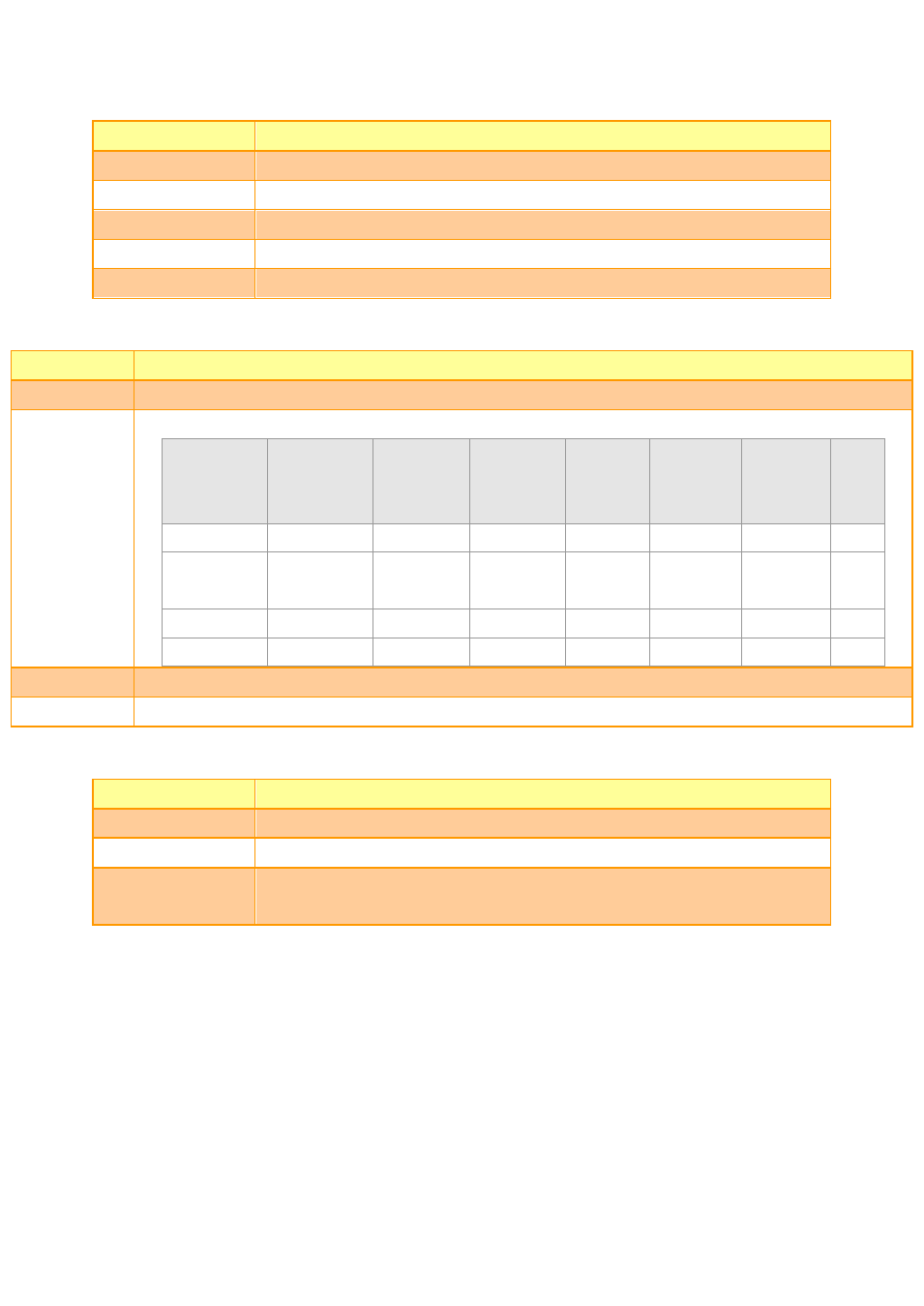
BIOS_DIS0#
BIOS_DIS1#
Selection straps to determine the BIOS boot device
BIOS_DIS1# BIOS_DIS0#
Chipset
SPI CS1#
Destination
Chipset
SPI CS0#
Destination
Carrier
SPI_CS#
SPI
Descriptor
Bios Entry
Ref
Line
1
1
Module
Module
High
Module
SPI0/SPI1
0
1
0
Module
Module
High
Module
Carrier
FWH
1
0
1
Module
Carrier
SPI0
Carrier
SPI0/SPI1
2
0
0
Carrier
Module
SPI1
Module
SPI0/SPI1
3
KB_RST#
Input to module from external keyboard controller that can force a reset.
KB_A20GATE
Input to module from external keyboard controller that can be used to control the CPU A20 gate line.
2.4.2.1.6 PCI Express Signals
Signal
Signal Description
PCIE_TX[0:4] +/-
PCI Express Differential Transmit Pair 0-4
PCIE_RX[0:4] +/-
PCI Express Differential Receive Pair 0-4
PCIE0_CK_REF+/-
Reference clock output for PCI Express lanes 0-7 and for PCI Express Graphics
lanes 0-15