Back panel front panel, Page 3 of 22 front and back panels – Altech UEC DSD4121RV User Manual
Page 4
Smartcard Slot
Behind the Front Panel Cover.
11
RESET
Reboots the decoder, i.e. if decoder freezes etc.
8
Page 3 of 22
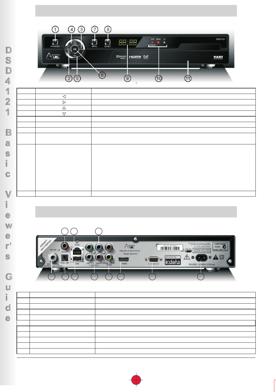
Front and Back Panels
Front Panel
LED Display
Displays the time (Standby Mode) or displays the selected
TV channel.
9
LEDs
Bi-colour
RED/GREEN
AMBER
GREEN
Indicates response to remote control commands and/or error mode
RED = Decoder in standby mode or an error condition has occurred.
GREEN = Normal operations.
Flashes = when there are incoming messages
Flashes = when RCU command received.
10
SAT IN
1
Connect to the LNB on dish
Power Input connector
Connect to your home AC mains outlet
11
Data Services
Connects to Rs323 (for software upgrade)
10
HDMI
Connects to the high definition (HDMI) input on TV or AV home theatre system
9
Composite Video
Connects to the video inputs on TV
8
Video =YPbPr
Connects to the YPbPr inputs on TV
7
Audio = Left & Right
Connects to the analog inputs on TV
6
USB
Connects to USB device (for software upgrade)
5
R J45
Connects to Ethernet (currently disabled in this version)
4
S/PDIF (Coaxial connector)
Connects to the Digital Audio coaxial input on TV or AV Home Theater System
3
TOSLINK (Optical connector)
Connects to the Digital Audio optical input on TV or AV Home Theater System
2
BACK PANEL
FRONT PANEL
STANDBY Button
1
Switches the decoder between ON and STANDBY modes.
MENU
Opens command menu for changing the setup.
7
OK
Accepts the selection.
6
Increases the volume level.
4
VOL
Changes to the previous available channel.
2
CH
Decreases the volume level.
5
VOL
Changes to the next available channel.
3
CH
4
3
7
8
1
2
5
6
9
10
11