Connecting peripherals, Figure 3, Flat view of milsystem i/o panel – ADLINK MilSystem 735 User Manual
Page 12: 8user’s guide milsystem, Figure 3. flat view of milsystem i/o panel, Milsystem setup, Mc-3 mc-2 mc-1 power
MilSystem Setup
8
User’s Guide
MilSystem
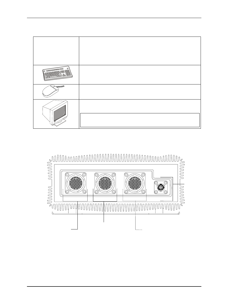
Figure 3. Flat View of MilSystem I/O Panel
Connecting Peripherals
7) Connect the MC-1 cable
to the MilSystem. See
illustrations of cables. See
for locations of
the MC connectors.
•
Refer to
for locations and descriptions of the connectors before
making connections or powering on the MilSystem.
•
Connect the USB or PS2 keyboard to the appropriate connector on the
MC-1 connector.
•
Connect the USB mouse (PS2 not supported) to the appropriate connec-
tor on the MC-1 connector.
•
Connect the CRT or LCD monitor through its 15-pin cable to the VGA
cable on the MC-1 connector.
CAUTION
The monitor must be connected to the MilSystem before
you power on the system, or the display ouput
automatically will switch from VGA to LVDS.
47
40
25
32
17
10
4
1
3
9
16
24
31
39
46
52
55
53
47
40
25
32
17
10
4
1
3
9
16
24
31
39
46
52
55
53
47
40
25
32
17
10
4
1
3
9
16
24
31
39
46
52
55
53
B
AD
C
8-4
MC-3
MC-2
MC-1
POWER
DC
Power
In
MC-3 - Parallel
and LVDS
MC-2 - USB3,
USB4, Fast
Ethernet, and
RS232/485/422
COM Ports
MC-1 - VGA, Ethernet,
PS2 Keyboard, Stereo
Audio Out, Stereo Line In,
Mic In, Power Button,
Reset Button, Power LED,
HDD Activity LED, SATA,
USB1 and USB2