4 block diagram, 5 functional description, Processor support – ADLINK TRL-40 User Manual
Page 17: Block diagram, Functional description, Figure 1-1: trl-40 block diagram, Introduction 7 trl-40
Introduction
7
TRL-40
1.4
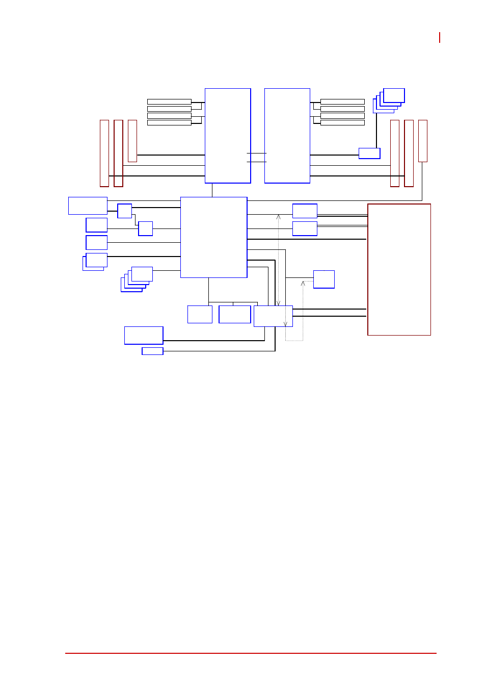
Block Diagram
Figure 1-1: TRL-40 Block Diagram
1.5
Functional Description
Processor Support
The TRL-40 is a dual processor design based on the Intel® Xeon
®
Processor E5-2600 family. One LGA-2011 socket connects to an
Intel C604 chipset through a 5 GHz Direct Media Interface (DMI).
The system clock generator is set by the processor delivering
100MHz host clock. Dual CPUs have their own onboard VRD
compliant to the VRM 12 specification. The VRD regulates+12V
from the DC-DC module to generate the required CPU core power
based on the CPU SVID. Each Xeon
®
E5-2600 processor has
dual-channel memory on 4 DIMMs supporting 800,1066, 1333,
and 1600 MT/s registered or un-buffered DIMM. Platform Environ-
ment Control Interface (PECI) for thermal monitoring and other
functions is supported.
Patsburg- B
QPI
Intel
Sandy Bridge EP
CPU 1
USB
Intel
I210AT
SPI
USB x4
QPI
LPC
B
A
C
K
P
A
N
E
L
Intel
Sandy Bridge EP
CPU 0
DMI x4
PCH
AST2300
IPMC
VGA
PCI-E x8
PCI-E x16
PCI-E x1
COM
WOL support
DDR3 1600 RDIMM
DDR3 1600 RDIMM
DDR3 1600 RDIMM
DDR3 1600 RDIMM
DDR3 1600 RDIMM
DDR3 1600 RDIMM
DDR3 1600 RDIMM
DDR3 1600 RDIMM
PCI-E x1
VGA
USB x 4
USB 2.0 x4
COM DSUB(RS232/422/485)
RJ45
PCI-E x16
PCI-E x16
PCI-E x16
PCI-E x16
PCI-E x16
PCI-E x16
PCI-E x16
PCI-E x8
PCI-E x1
Intel
I210AT
RJ45
SATA
SATA3.0 x1
RS232
ALTERA
Port_80
Port_80
Pin Header
WOL support
PCI-E x4
PCI-E x 2
Marvell
SATA
RAID
PCIE x1
MUX
PCI-E mini card
(mSATA or PCIE)
SATA
MUX
SATA3.0 x1
SATA 3.0 x4
SATA
SATA2.0 x2
USB x 2
BIOS
NC_SI
USB x1
Console
Pin Header 2x5
P:2.54mm
PCI-E x8