3 getting started, 1 jumper settings, Getting started – ADLINK nanoX-BASE User Manual
Page 14: 1 jumper, Settings
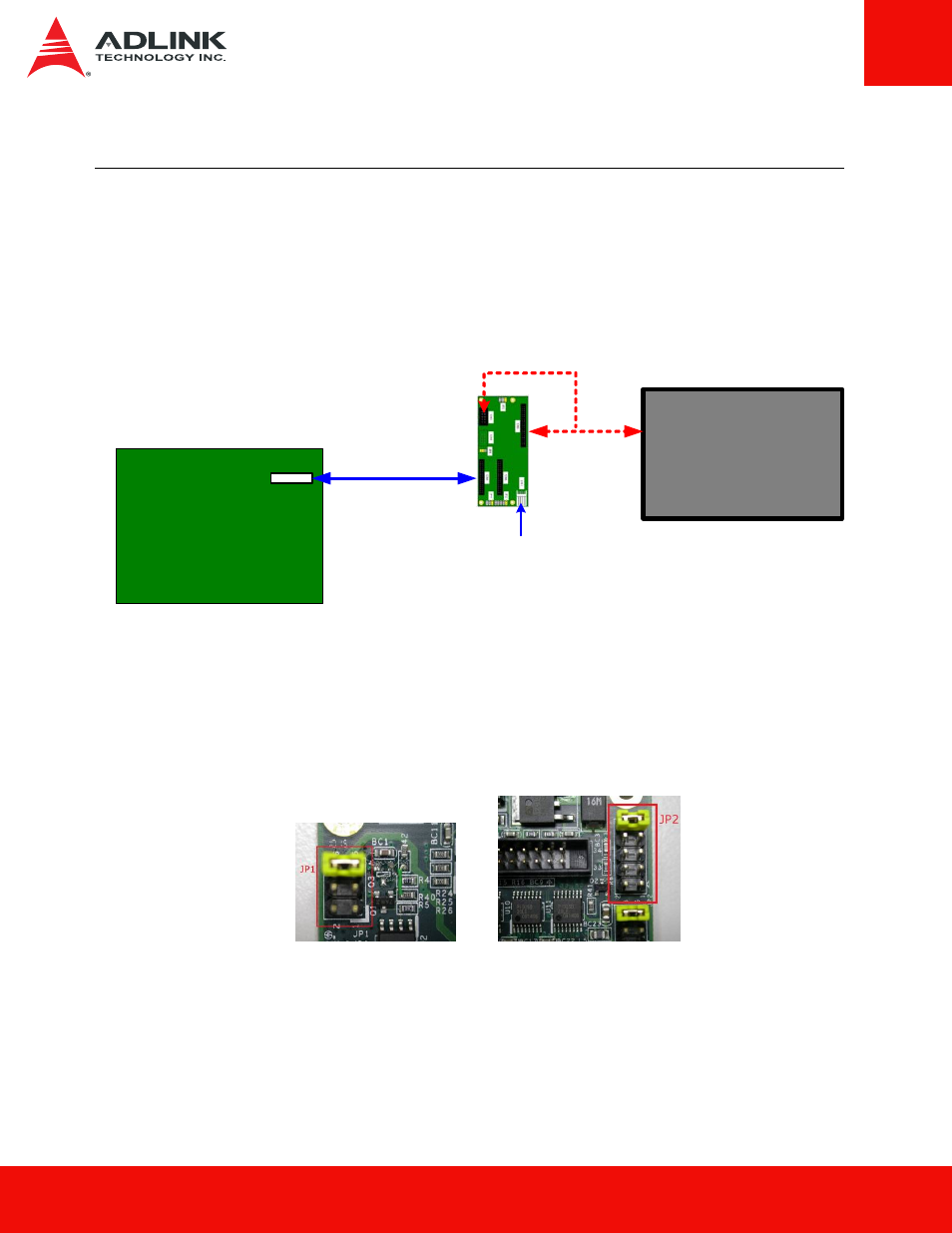
3 Getting Started
The example instructions below describe how to use the
FPTB to connect an ADLINK
reference carrier board to a TTL display: In this configuration, the FPTB provides LVDS-to-
TTL conversion and backlight control. The user must provide the cable connection from the
FPTB's TTL output and backlight control connectors to the TTL panel inputs.
TTL Display
FPTB
TTL
Signal
5V and
12V Input
Backlight
control
nanoX/Express-BASE
Carrier Board
LVDS output
LVDS-to-LVDS cable
ADLINK P/N: 30-20449-0000
3.1 Jumper Settings
Make sure the
Backlight Voltage jumper (JP1) and Panel Voltage jumper (JP2) are
correct for the display panel you are using.
Set the
LVDS/TTL Mode jumper (JP4) to TTL Output Active (short pins 1-2).Set the
Backlight Control Mode jumper (JP5) to PWM or Voltage Level as appropriate for your
display.
14 FPTB
User's
Manual