3 operations, 1 connection configuration, Connection configuration – ADLINK LPCIe-3488A User Manual
Page 33: Figure 3-1: standard gpib connector, 3operations
Operations
23
LPCIe/LPCI/USB-3488A
3
Operations
This chapter describes the operation theory of GPIB bus and the
basic architecture of ADLINK’s GPIB interface cards.
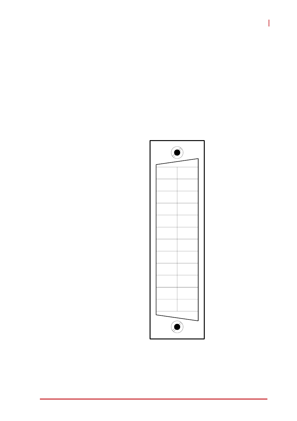
3.1 Connection Configuration
The GPIB bus has 24 lines which are divided into 16 signal lines
and 8 ground return or shield drain lines. The 16 signal lines can
be divided into 8-bit parallel data transfer bus and 8 control lines.
The 8 control lines contain 5 system management lines and 3
handshake lines
Figure 3-1: Standard GPIB Connector
1
2
3
4
5
6
7
8
9
10
11
12
13
14
15
16
17
18
19
20
21
22
23
24
Shield
ATN
SRQ
IFC
NDAC
NRFD
DAV
EOI
DIO4
DIO3
DIO2
DIO1
Signal Ground
GND (TW PAIR W/ATN)
GND (TW PAIR W/SRQ)
GND (TW PAIR W/IFC)
GND (TW PAIR W/NDAV)
GND (TW PAIR W/NRFD)
GND (TW PAIR W/DAV)
REN
DIO8
DIO7
DIO6
DIO5
This manual is related to the following products: