Table 1-3: digital i/o and power pin assignment – ADLINK NEON-1020 User Manual
Page 20
10
Introduction
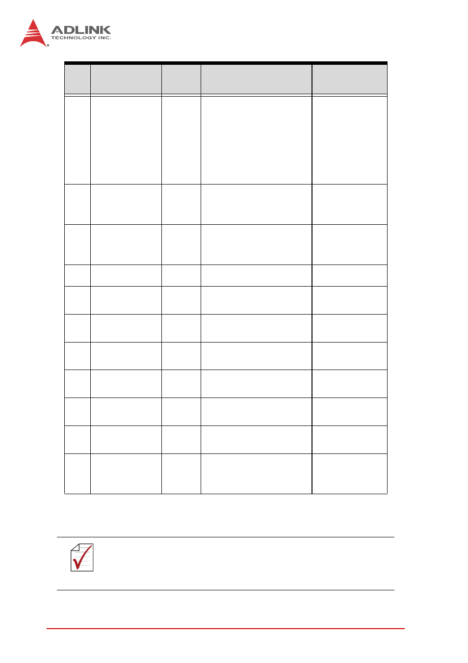
Table 1-3: Digital I/O and Power Pin Assignment
7
PWM light
control out (-)
Output
PWM LED control out
negative, for
connection to LED
lighting device; Power
source of LED current
control is shared
System PWR
Black
8
System PWR Input
Power input w/ input
range +12V ~ +24V
+/-10%
Gray
9
System PWR
Input
Power input w/ input
range +12V ~ +24V
+/-10%
Red
10
RS232 TXD
Output RS-232 transmit
Violet
11
DO2/
Strobe out 2
Output
Open-collector output 2
or strobe out 2
Gray/Pink
12
DO0/
Strobe out 0
Output
Open-collector output 0
or strobe out 0
Red/Blue
13
DI3
Input
Digital input signal
source 3
White/Green
14
DI0
Input
Digital input signal
source 0
Brown/Green
15
DI2
Input
Digital input signal
source 2
White/Yellow
16
DI1
Input
Digital input signal
source 1
Yellow/Brown
17
GND
GND
Ground, reserved for
use with ground from
power supply
White/Gray
NOTE:
NOTE:
The negative pin of Digital OUT and Digital IN is GND.
Pin
Signal
Type
Description
17-Pin M12
Pigtail