4 isolation input registers, Isolation input registers, Isters – ADLINK cPCI-7252 User Manual
Page 33: Table 3-5: relay output
Registers
23
open signal line is ‘open’. Bit value ‘1’ means the relay is ener-
gized and the normal open signal line is now closed.
The initial bit values of the control register are all ‘0’ and the status
of the relay can be readback from the readback register. If the
relay is open, the corresponding bit value read is ‘0’. If the relay is
closed, the bit value read is ‘1’.
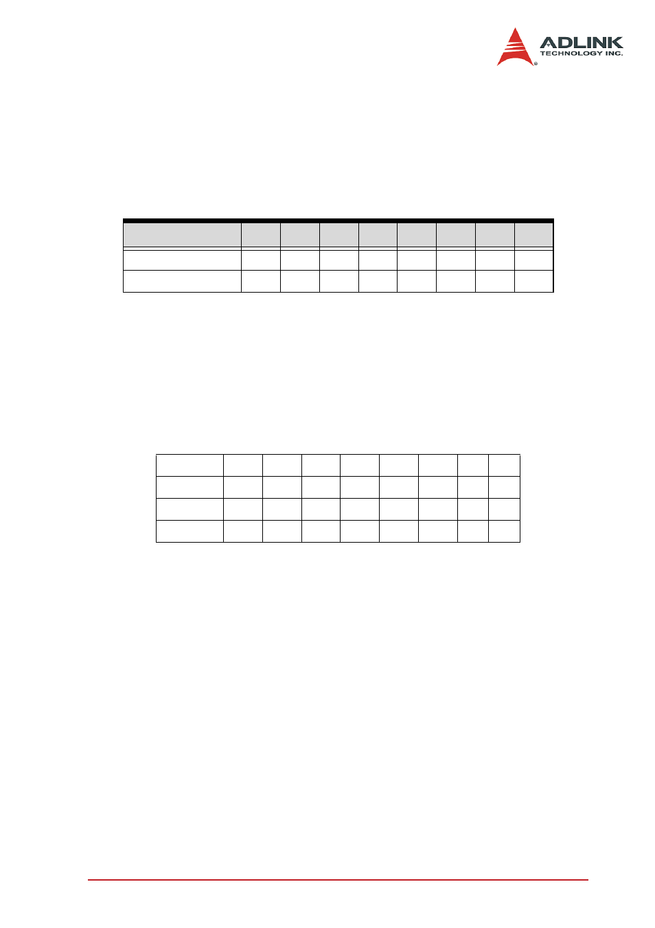
3.4 Isolation Input Registers
There are 8 isolated input channels on the PCI-7250 / 7251 board.
The status of the 8 channels can be read from the isolation input
register. Each bit corresponds to each channel. Bit value “1”
means input voltage is high and “0” means input voltage is low.
Note:
Bits 8-15 are for cPCI-7252 only
Bit
7
6
5
4
3
2
1
0
Relay Output
DO7 DO6 DO5 DO4 DO3 DO2 DO1 DO0
Output Readback RB7 RB6 RB5 RB4 RB3 RB2 RB1 RB0
Table 3-4: Data Format of Relay Output and Readback Status Registers
Bit
7
6
5
4
3
2
1
0
Iso. Input DI7
DI6
DI5
DI4
DI3
DI2 DI1 DI0
Bit
15
14
13
12
11
10
9
8
Iso. Input DI15 DI14 DI13 DI12 DI11 DI10 DI9 DI8
Table 3-5: Relay Output