Acrosser AMB-N280S1 User Manual
Page 14
14
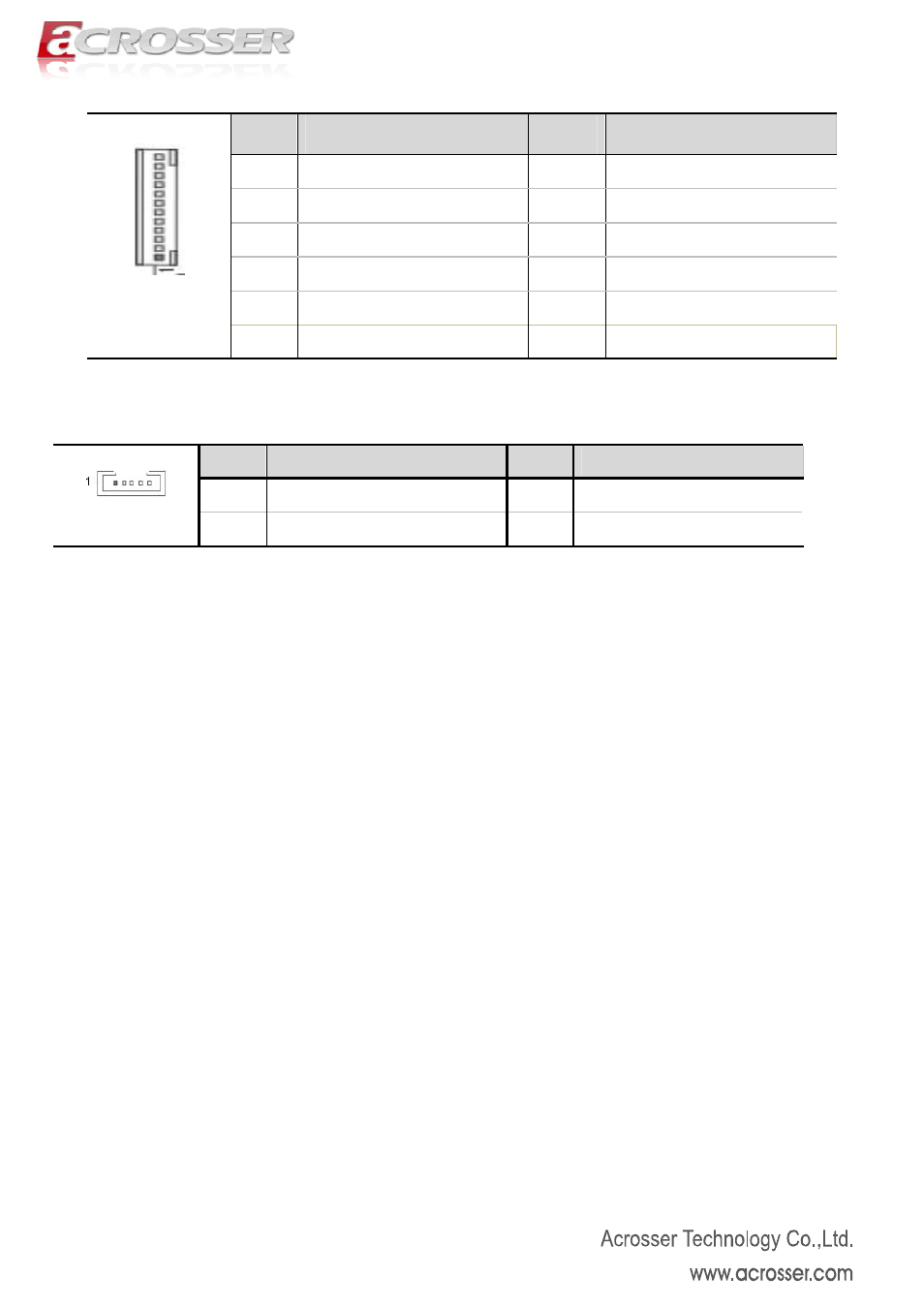
[19] VGA Header(12*1 Pin 2.00 mm)(Reserve for Test)
Pin
Definition
Pin
Definition
1 CRT_ON 2 VSYNC
3 HSYNC 4
GND
5 RED 6 GND
7 GREEN 8
GND
9 BLUE 10 GND
J_VGA1
11 DDCDAT 12 DDCCLK
[20] ATX2 Power Output Header (4*1 Pin 2.54mm)
Pin
Definition
Pin
Definition
1
+12V
2
GND
ATX2
3
GND
4
+5V
[1] The Mini-PCIe1 supports 3G module but cannot supports mSATA module.
And Mini-PCIe2 supports mSATA module only.
[2]The output default value (Pin 1 of COM1,COM3) is DCD and also can be 5V or 12V by changing the
hardware.
[3] The output default value (Pin 9 of COM3) is RI and also can be 5V or 12V by changing the hardware.
[4] The output default value (Pin 1 and Pin 9 of COM3,COM4) is NC, and also can be 5V or 12V by
changing the hardware.
[5] It cannot use USB Hub with power adaptor that connects to all USB port.