Operating controls and adjustments, Locking switch in the “off” position, Adjusting sanding belt tension and tracking – Delta 31-552 User Manual
Page 8
8
OPERATING CONTROLS AND ADJUSTMENTS
STARTING AND STOPPING
THE ABRASIVE FINISHING
MACHINE
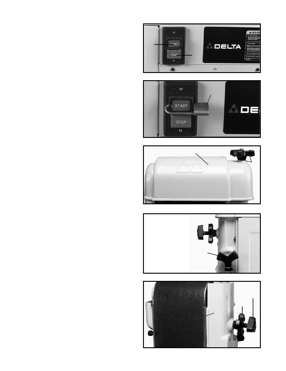
To start the machine, push “ON” button (A) Fig. 10. To
stop the machine, push “OFF” button (B).
Fig. 10
A
B
LOCKING SWITCH
IN THE “OFF” POSITION
IMPORTANT: When the machine is not in use, the switch
should be locked in the OFF position using a padlock (A)
Fig. 11, with a 3/16" diameter shackle to prevent
unauthorized use.
Fig. 11
A
ADJUSTING SANDING BELT
TENSION AND TRACKING
YOUR MACHINE IS SHIPPED WITHOUT BELT TEN-
SION APPLIED TO THE SANDING BELT. BEFORE
OPERATING THE MACHINE IT IS VERY IMPORTANT
THAT THE SANDING BELT IS PROPERLY ADJUSTED
FOR CORRECT BELT TENSION AND IS TRACKING
PROPERLY, AS FOLLOWS:
DISCONNECT MACHINE FROM POWER SOURCE.
1.
Remove lock knob and washer (A) Fig. 12. Remove
top cover (B).
2.
Turn the belt tension handle (C) Fig. 13, clockwise to
increase belt tension. Correct tension is determined by
two things:
(1) The belt should be flat on the platen.
(2) The belt should be sufficiently tensioned to
prevent slipping on very heavy work. For ordinary
work, a tension just sufficient to take the curl out of
the belt is recommended.
3.
Loosen tracking lock knob (D) Fig. 14, and while
rotating the belt (F) by hand, tighten or loosen tracking
knob (E) until the belt is running true on the pulleys.
4.
Then jog the machine on and off to check further if
the belt is tracking properly. If the belt is leading to one
side or the other, very gently turn the tracking knob (E)
Fig. 14, clockwise to move the belt toward the adjusting
screw and counterclockwise to move the belt away from
the adjusting screw while jogging the machine on and
off.
5.
A final adjustment can be made with the motor
running. THIS ADJUSTMENT IS USUALLY VERY
SLIGHT. After the belt is tracking properly, tighten the
lock knob (D) Fig. 14, being careful the adjusting screw
(E) does not turn.
6.
Replace top cover (B) Fig. 12.
Fig. 12
Fig. 13
B
A
C
Fig. 14
D
E
F