Power lock, Power/ground, Connector here – Directed Electronics A1200/4 User Manual
Page 18: A600/4, End plate diagram, Front plate diagram
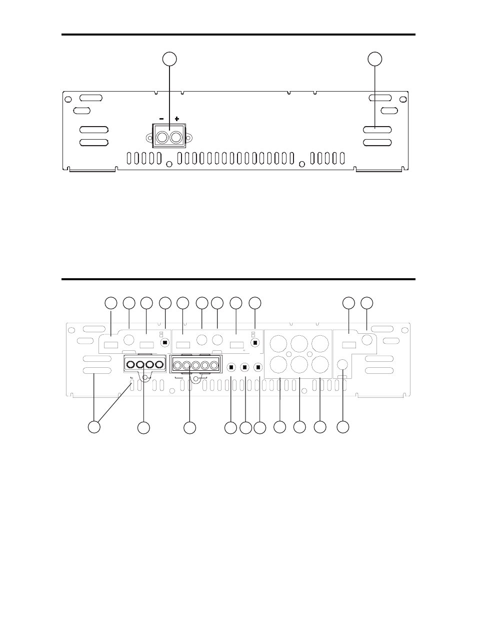
A600/4
END PLATE DIAGRAM
1. Power/Ground
PowerLock
TM
: After you have securely
connected your power and ground wires, plug in the Power/Ground
PowerLock
TM
connector here.
2. Cooling Plenums: Maintain a minimum 2” clearance around
cooling plenums for proper amplifier cooling.
A1200/4
FRONT PLATE DIAGRAM
1. Cooling Plenums: Maintain a minimum 2” clearance around
cooling plenums for proper amplifier cooling.
2. Rear Speaker Connector: Plug in the
PowerLock
TM
connector
here.
3. Front Speaker/Remote Connector: Plug in the
PowerLock
TM
connector here.
LP
FULL HP
GAIN
MIN MAX
FRONT
FREQ
30 4K
OUTPUT
REAR
R
FRONT
IN
IN
OUT
L
LP
FULL
HP
FREQ
30 4K
LP
FULL
HP
GAIN
MIN MAX
REAR
SOURCE
INT
EXT
QBASS ATT
2 1
-12dB
FREQ
FR- FR+ REM FL+ FL-
BRIDGED
BRIDGED
RR- RR+ RL+ RL-
FREQ
LP
FULL
HP
30 4K
OUTPUTS
LP
FULL
HP
SOURCE
SUM
REAR
11
12
13
14
15
16
17
18
19
20
21
1
7
8
9
10
5
4
3
2
6
1
2
17