Figure 2, Operation, Maintenance & replacement parts – Ace 73-100 User Manual
Page 3
Attention! The text in this document has been recognized automatically. To view the original document, you can use the "Original mode".
•U-
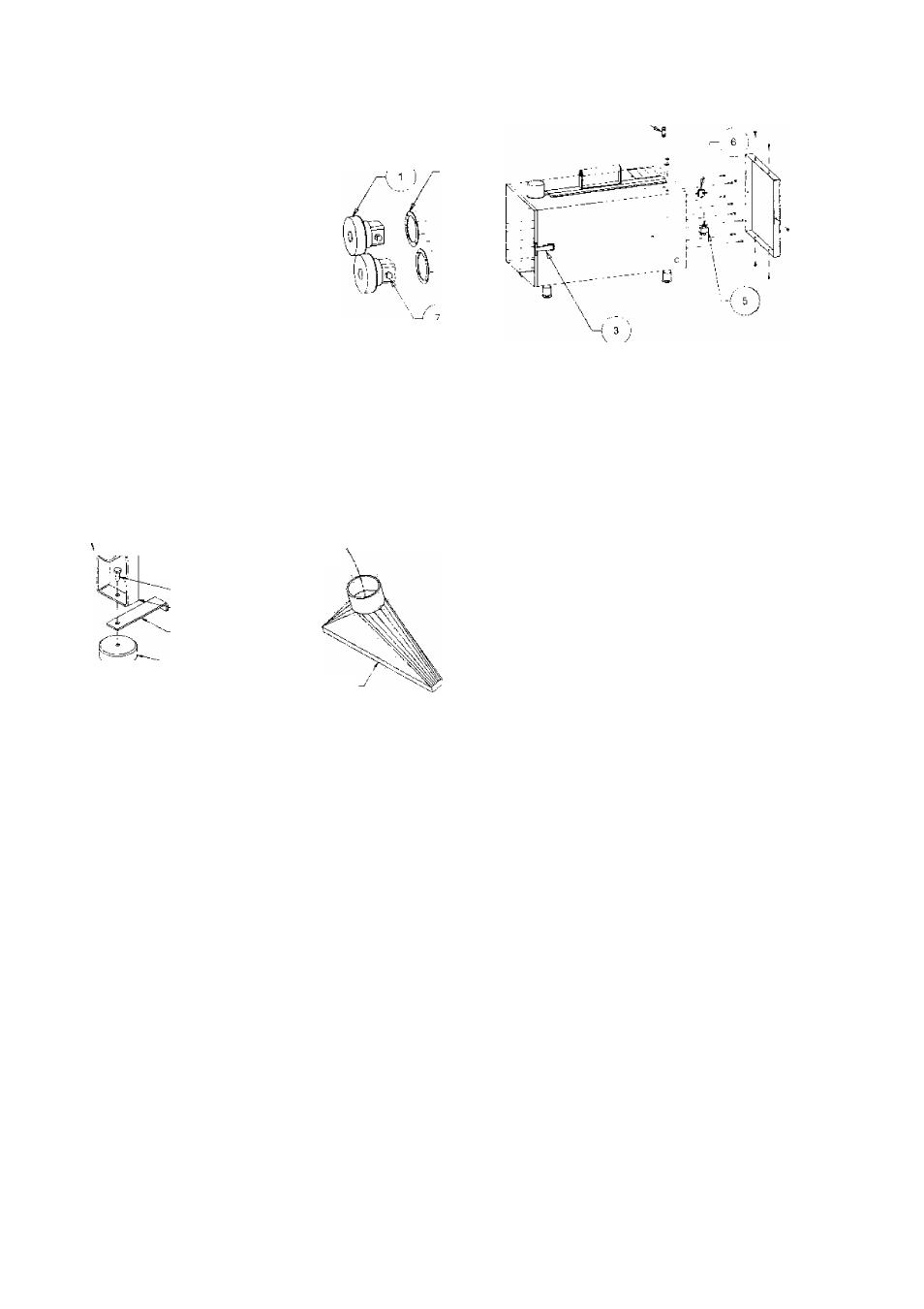
PRE-FILTER
IMSTALL PLEATS VERTICALLY
AS SHOWN
FLA- FIBER WAE.
(3 £A:
Figure 1
\
у SHUT-LOCK. A'*SHt4 IK
,
S
f
f .i
flFK TUBf ASSY
41 EA)
- HFK. HFA,":- ROlY i.'fl
?Q
к
2/4
i;i ÉAÌ
’■■•-— BRACKET HOSt SUPPORT
4T fA:
-sui>poRT
lfo
<1 CA)
MAGNCrrC BASI
(1 FAI
Ф'-.
STEtL
FuAf
WAS-tW
(1 EA;
HtX Ns."
(T EA|
RECTANGULAR S^OZZLF
О EA)
Figure 2
OPERATION
Your ACE Industrial Products machine is designed as a
source capture device, i.e., it is intended to eliminate
smoke and particulate at their point of origin. Keeping this
in mind, the machine should be operated in the following
manner:
Re-read the section on Safety Warnings & Cautions
before proceeding any further
1
Place the machine on a flat, level surface Pick a
location that will allow unrestricted flow of the exhaust
air to the atmosphere
2
For units with wheels or casters, lock the wheels or
block the wheels.
3
Place the collection nozzle as close to the work as
practical without interfering with the operator Secure
the nozzle if necessary.
4
Using the ON/OFF switch, turn the machine on.
Should the motor not start, or should the machine
make unusual noises, immediately turn the machine
off and seek trained maintenance personnel. Do not
continue to use the unit.
5
Upon completion of the specific manufacturing or
welding operation, turn the machine off. Continuous
running of the unit will reduce the life of the filter and
the motor brushes as well as increase utility cost.
6
When the "dogged" fitter light indicates that the filter
is clogged, turn the machine off and remove power
cord from its power source
See the section on installation and use the reverse
process to remove the dirty filters Re-install the new
filter and reconnect the machine to its power source
MAINTENANCE & REPLACEMENT PARTS
FILTERS:
As previously stated in the "Theory of Operation" section
of this manual, the "clogged" filter indicator light will light
whenever the differential pressure across the filter
indicates that the filter is clogged. When opening the unit,
there are no vacuum hoses to disconnect since the
pressure sensing is accomplished by measuring at the
inlet and inside the suction chamber. The differential
pressure trip point is preset and is not field adjustable.
If the “clogged" filter light should light, the pre-filter should
be changed first, since it is the least expensive of the two.
By changing the pre-filter on a regular basis, the main
filter will last up to 50% longer in most applications If
the light still lights after the pre-filter is changed, the main
filter is dogged and must be changed.