Model 4e769b, Maintenance – Desa 4E769B User Manual
Page 9
Dayton Operating Instructions and Parts Manual
9
Model 4E769B
Version B - For Reduction
G016.J
®
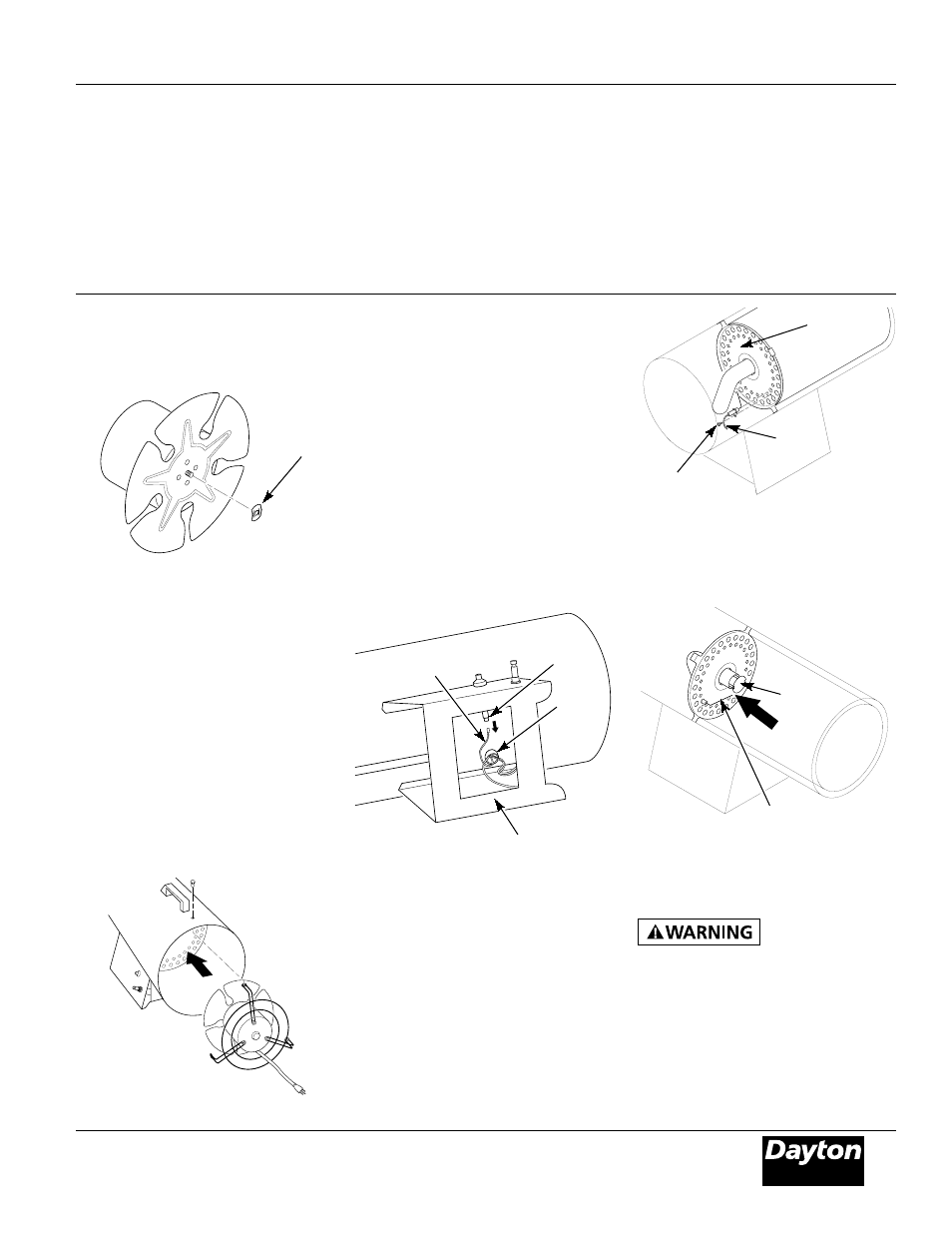
Ignitor
Ignitor
Mounting
Screw
Rear Head
Figure 15 - Removing Ignitor Mounting
Screw and Ignitor
7. Set gap between ignitor electrode and
target plate to .17" (See Figure 16).
Figure 13 - Replacing Motor and Fan
Guard into Heater
9. Place motor and fan guard into rear
of heater shell. Make sure power cord
is properly located (See Figure 13).
10.Insert three screws through heater
shell and into fan guard. Tighten
screws firmly.
Target
Plate
Ignitor
Electrode
Figure 16 - Clearance Between Ignitor
Electrode and Target Plate
8. Test for spark.
Make sure heater
is disconnected
from propane supply. Heater could
ignite causing severe burns.
Push piezo ignitor button and
watch for spark between ignitor
electrode and target plate.
9. Place motor and fan guard into
rear of heater shell (See Motor,
page 8, steps 9 and 10).
3. Use pliers to remove the fan nut from
front of motor shaft (See Figure 12).
Figure 12 - Removing Fan Nut From
Motor Shaft
4a. If replacing fan, remove old fan
and discard. Go to step 7 below.
4b. If cleaning fan, remove fan. Be careful
not to damage the fan blade pitch.
5. Clean fan using soft cloth moist-
ened with kerosene or solvent.
6. Dry fan thoroughly.
7. Place fan onto motor shaft.
IMPORTANT: When placing fan onto
motor shaft, make sure part number
stamped on fan is facing motor.
8. Attach fan nut to end of motor
shaft. Tighten fan nut firmly.
IGNITOR
1. Remove motor and fan guard from
heater (See Motor, page 8, steps 1
and 2).
2. Remove black ignitor wire from
piezo ignitor. Access ignitor wire
through underside of heater base
(See Figure 14). Push wire up
through bushing in heater shell.
3. Remove ignitor mounting screw
from rear head using nut-driver or
standard screwdriver (See Figure 15).
4. Remove ignitor from rear head.
5. Install new ignitor. Attach ignitor to
rear head with ignitor mounting screw.
6. Run ignitor wire from new ignitor
through bushing in heater shell.
Attach ignitor wire to piezo ignitor.
Figure 14 - Removing Ignitor Wire from
Piezo Ignitor
Piezo
Ignitor
Bushing
Ignitor Wire
Underside of
Heater Base
Gap
Area
Fan Nut
Maintenance
(Continued)