Install trim (shower and tub spout), Finishing installation, Install handles – American Standard Hampton 7220.702 User Manual
Page 2: Test installed faucet, Service
Attention! The text in this document has been recognized automatically. To view the original document, you can use the "Original mode".
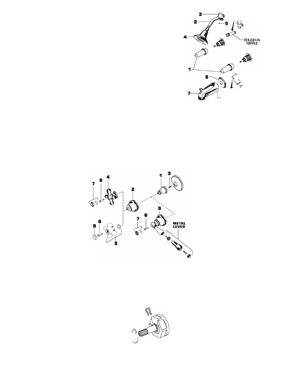
INSTALL TRIM (SHOWER AND TUB SPOUT)
NOTE; PROTECT FINISH ON SHOWER ANO TUB TRIM WHEN INSTALLING.
Remove PLASTER GUARDS (1J from valve body by unthreading and pulling off.
Remove rough-in nipple from shower elbow.
Apply sealing tape to threads on both ends of SHOWER ARM (2) and install
SHOWER ARM (2) with SHOWER ESCUTCHEON (3) into shower elbow.
Thread SHOWER HEAD (4) onto end of SHOWER ARM (2). Push SHOWER
ESCUTCHEON (3) against finished wall. Tighten SET SCREW (5).
Remove pipe cap from tub filler pipe. Prepare TUB FILLER PIPE, ELBOW and
1/2" C.W.T. SPOUT NIPPLE. Final length of SPOUT NIPPLE to be 1" from
finished wall.
Push SPOUT ESCUTCHEON (
6
) onto filler pipe flush against finished wall.
Push TUB SPOUT (7J onto filler pipe until tight against SPOUT ESCUTCHEON (6).
Tighten clamp screw in SPOUT (7) to secure TUB SPOUT (7) to rough-in nipple.
SHOWER
ELBOW
---- ROUGH-IN
NIPPLE
-------PIPE CAP
CLAMP SCREW
FINISHING INSTALLATION
Remove caps from roughing-in nipples.
Remove PLASTER GUARD by turning counter-clockwise and pulling.
If VALVE BODY is roughed in SHALLOW (more than 2-1/2")
screw SLEEVE in ESCUTCHEON facing front of ESCUTCHEON.
If VALVE BODY is roughed in DEEP (less than2-1/2")
screw SLEEVE in ESCUTCHEDN facing back of ESCUTCHEON.
Assemble RUBBER RING to ESCUTCHEON.
Screw ESCUTCHEON and SLEEVE onto VALVE COVER against wall.
Install SHOWER ARM, SHOWER ARM FLANGE and TUB SPOUT.
SHALLOW ROUGH-IN
MORE
THAN
2-^/2"
—►
SLEEVE
VALVE
COVER
-RUBBER
RING VALVE-
BODY
OEEP ROUGH-IN
LESS
THAN
2-1/2” _
SLEEVE
Ld
ESCUTCHEON
D
INSTALL HANDLES
FOR CROSS HANDLES
Turn VALVE into OFF position.
Push ADAPTER (1J into HANDLE
BASE (2) in a way that the male
square on the ADAPTER (1J fits in
the female square of the
HANDLE BASE (2).
Push HANDLE BASE (2) and
ADAPTER (1) onto VALVE STEM (3).
Push CROSS HANDLE (4, 5) onto
HANDLE BASE (2).
Install HANDLE SCREW (6) and tighten.
Push INDEX CAP (7, 8) in top of
CROSS HANDLE.
FOR LEVER HANDLES
Turn VALVE into OFF position.
Push ADAPTER (1) into HANDLE BASE (S)
in a way that the male square on the
ADAPTER (1J fits in
he female square of the
HANDLE BASE (S).
Push HANDLE (9) and ADAPTER (1)
onto VALVE STEM (3).
Check alignment, if not
satisfactory aligned;
■ Push out ADAPTER (1J carefully.
■ Turn ADAPTER (1) either 45'or
90' so that male square on
ADAPTER (1J catches different
female square in HANDLE BASE (S).
■ Assemble and tighten HANDLE SCREW (6).
Push INDEX CAP (7J in top of HANDLE (S).
TEST INSTALLED FAUCET
Turn HANDLES into "off" position.
Turn on water supplies and check all connections for leaks.
Operate both HANDLES to flush water lines thoroughly.
Check SHOWER HEAD and SPOUT connections for leaks. Operate
DIVERTER for proper operation. Turn handles into DFF position.
SERVICE
SPRING
CLIP I
To change direction of handle rotation, proceed as follows:
■ Turn valve to DFF position.
■ Pull out INDEX CAP and remove
HANDLE SCREW.
^
■ Pull out LEVER BALL from HANDLE BASE.
*
■ Unscrew HANDLE BASE and remove ADAPTER
■ Remove SPRING CLIP
\T\\
■ Lift STDP WASHER, turn 9D and replace.
* Replace SPRING CLIP
i___ STOP
■ Reinstall HANDLE. (See step three).
WASHER
If spout drips, operate handles several times from OFF to ON
position. Do not force - handles turn only 9D .
CARE:
DO: SIMPLY RINSE THE PRODUCT CLEAN
WITH CLEAR WATER. DRY WITH A SOFT
COTTON FLANNEL CLOTH.
DO NOT: DO NOT CLEAN THE PRODUCT
WITH SOAPS, ACID, POLISH, ABRASIVES,
HARSH CLEANERS, OR A CLOTH WITH A
COARSE SURFACE.
U S 6 0 4 0 6 R E V . 1 . 1