Systems features and basic operation – ATI Technologies Lawn Mower User Manual
Page 17
Attention! The text in this document has been recognized automatically. To view the original document, you can use the "Original mode".
SYSTEMS FEATURES AND BASIC OPERATION
• If the Rod Eye Receiver indicates the
plane of laser light is too high or too
low, have a second person rotate the
Rotating Laser on the tripod in small
steps until the Rod Eye Receiver indi
cates “On Grade.”
7. Enter on the Rotating Laser the required
percent of grade for each axis and allow the
Rotating Laser to level itself again.
8. Bench the machine. See the “Benching and
Operating Your Machine” procedure in this
section.
Method Two:
NOTE: This procedure requires that the elevations
of the grade stakes are correct and aligned
to the slope or percent of grade required.
1. Set a minimum of two surveyed grade
stakes. The stakes must have elevation
information.
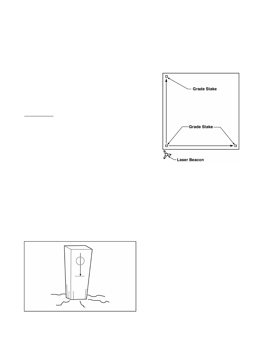
2. Place the Rotating Laser a few feet (meters)
behind the first grade stake and in line with
one of the far grade stakes (it is not critical
to align the Rotating Laser exactly). (Refer
to Figure 9.)
NOTE: Follow the guidelines at the beginning
of this section when placing the Rotating
Laser.
3. Switch on the Rotating Laser. Level the
Rotating Laser.
4. Roughly align one of the axis to the grade
stakes by sighting over the top of the
Rotating Laser (Refer to Figure 7).
5. Set both the counters on the Rotating Laser
to the required percent of grade (If needed,
see the Rotating Laser Operation Manual).
Figure 9. Method Two: Align Rotating Laser with Grade
Stakes
NOTE: The Grade Rod must be held plumb for
each of the readings taken in the following
steps.
6.
Establish the H.I. (height of the instrument)
for the plane of laser light.
a. Align the bottom of the Grade Rod to the
mark on the near grade stake.
b. Adjust the Rod Eye Receiver up and down
until it indicates “On Grade.”
c. Adjust the Rod Eye Receiver for any cut
or fill amount indicated by the grade stake.
• If the grade stake shows a cut, extend
the Grade Rod and Rod Eye by the
amount shown as a cut.
• If the grade stake shows a fill, lower the
Rod Eye by the amount shown as fill.
Figure 8. Grade Stake with Elevation Mark
7