Equipment set-up, Systems features and basic operation – ATI Technologies Lawn Mower User Manual
Page 13
Attention! The text in this document has been recognized automatically. To view the original document, you can use the "Original mode".
SYSTEMS FEATURES AND BASIC OPERATION
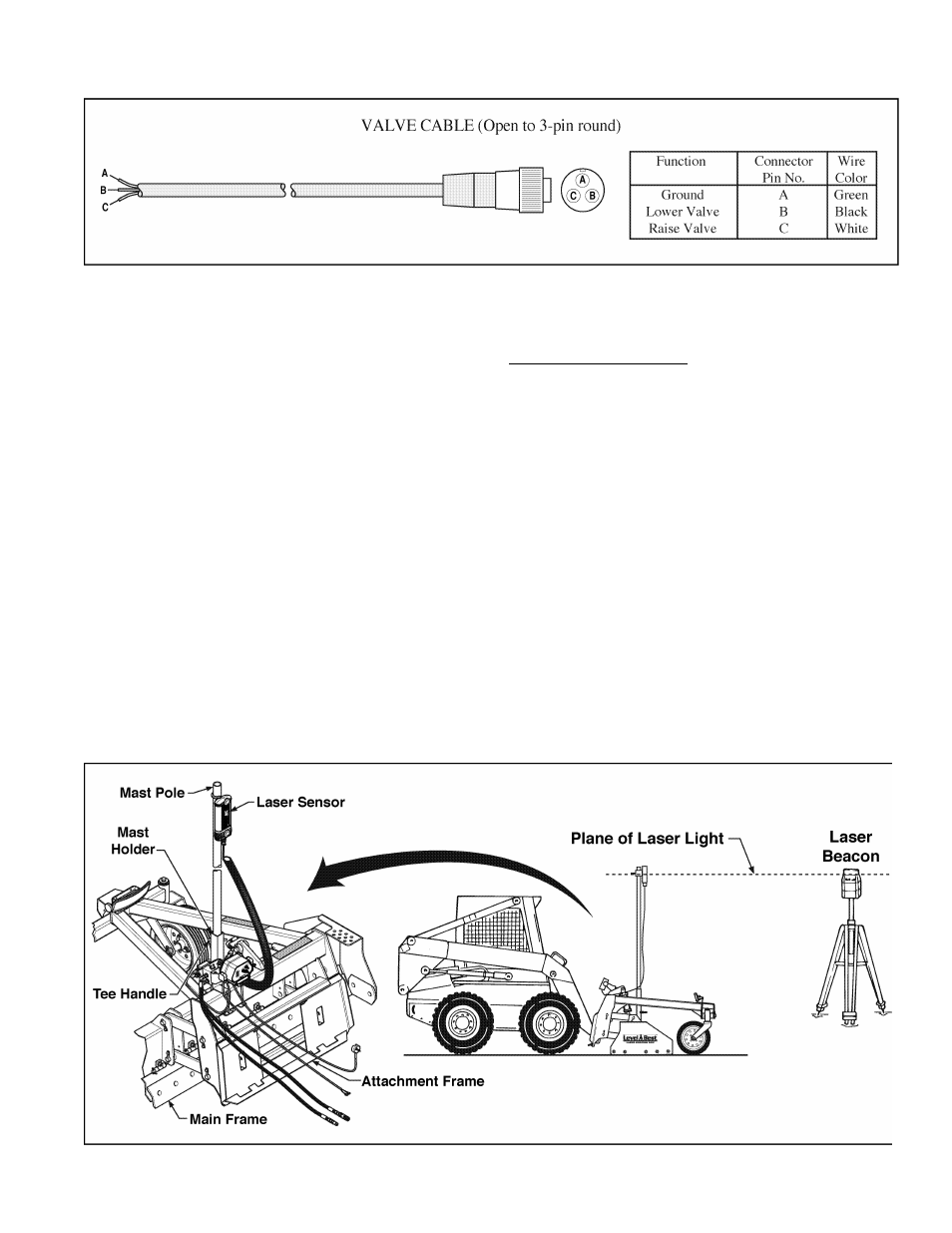
Figure 2. Valve Connection Details
Hydraulic Valve
The hydraulic valve is mounted on the frame of the
Laser Grading Box. It is an electrically-actuated
double-acting, single-section valve. Hoses and
quick-couplers to attach it the tractor’s auxiliary
hydraulics are included with the hydraulic kit.
An electrical cable is also provided. One end of the
cable has a 3-pin connector for the valve. The other
is open and can be attached to the Control Panel of
the automatic control system as required. Refer to
Figure 2 for wiring details of the cable and conduc
tor functions.
The valve accepts a 12 VDC proportional current
signal from the Control Panel.
If you require a proportional time or 24 volt valve,
contact ATI Corporation.
EQUIPMENT SET-UP
Skid Steer Grading Box
1. Provide power to the Control Panel from the
skid steer’s electrical system. Usually this
involves a direct hookup to the battery.
2. The Laser Grading Box should be positioned
on a level area for attaching to the skid steer.
Start the skid steer and drive up to the attach
ment plate and secure per the manufacturer’s
directions. The Level Best quick-attach plate
is designed to be universal.
NOTE: If the skid steer’s pins do not fit securely
into the rectangular holes at the base of
the attachment plate, these holes can be
notched larger to accept the pins.
Figure 3. Components of the Automatic Control System on a Skid Steer
3