Wiring schematic – Autostart One-way Automatic Transmission Remote Starter with Full Alarm System User Manual
Page 4
Attention! The text in this document has been recognized automatically. To view the original document, you can use the "Original mode".
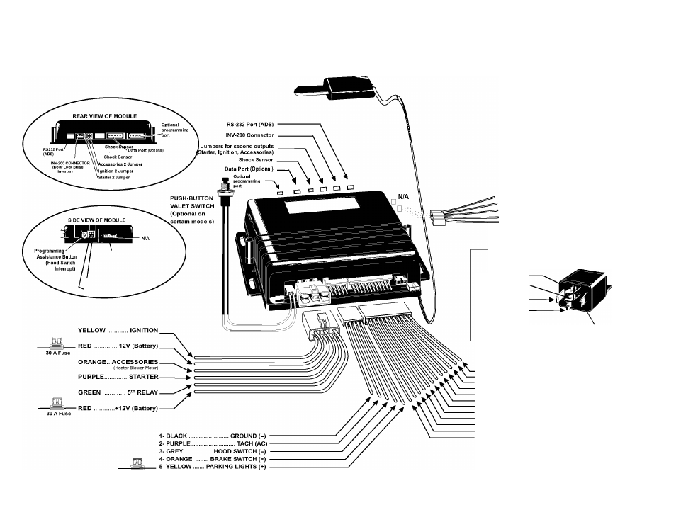
WIRING SCHEMATIC
5. YELLOW.................... (-) PARKING LIGHTS input
4. BLACK/BROWN......... N/A
3. BLACK/GREEN..........(-) AUX2 output
2. WHITE/PURPLE........ (-) HORN output
1. GRAY/LIGHT BLUE ... N/A
5. YELLOW................... (-) PARKING LIGHTS
4. BLACK/BROWN....... N/A
3. BLACK/GRENN........ (-) AUX2 output
2. WHITE/PURPLE....... (-) HORN output
1. GREY/BLUE.............. N/A
'TACH Threshold: HIGH
TACH Threshold: NORMAL
Optional Starter Kill Relay
N/A87
STARTE R WI RE 87A
(Solenoid Side)
IGNITION (+) 85
STARTER WIRE 30
(Key Side)
86
Start Kill Output (-)
12- YELLOW.................................. (+) Glow plug input
11- GREY....................................... (-) Negative Door input
10- WHITE.......................................(-) GROUND out when running
9- PURPLE..................................... (+) Siren output
8- ORANGE.................................... N/A
7- WHITE/ORANGE........................ (-) Starter kill output
6- BLUE/WHITE.............................. (+) Positive Door input
5- WHITE/GREEN........................... (-) DISARM
4- WHITE/BROWN.......................... (-) REARM
3- GREEN....................................... (-) UNLOCK
2- BROWN...................................... (-) LOCK
1- BLUE.......................................... (-) TRUNK output
V5.0 TL - October 3, 2006
15 A Fuse